The American Society for Testing and Materials (ASTM) International Committee F03 on Gaskets recently released the latest standard practice to derive gasket design constants for the proper design of bolted flanged joints (BFJs): ASTM F2836-18. End users of gaskets can then use these gasket constants for proper BFJ design using calculation methods that are currently being developed by a special working group of American Society of Mechanical Engineers (ASME) Boiler and Pressure Vessel Code (BPVC) Section VIII at the time of this publication. In this article, the current test procedure, the mathematical models of the test evaluation and the calculation of the characteristics are described and discussed.
Background
Most industry professionals are aware that BFJs used in fluid service are complex mechanical systems. In order to create a high-performing BFJ, a designer needs to carefully consider not only the service conditions the BFJ will encounter, but also the performance characteristics inherent to the components of the BFJ. The gasket itself is one of these critical, yet often overlooked, components, and efforts to determine and quantify the performance characteristics of gaskets have been ongoing for decades.
The newest of these efforts to be published in the United States is ASTM F2836-18: Standard Practice for Gasket Constants for Bolted Joint Design (commonly referred to as the Room Temperature Tightness Test, or ROTT). The design constants produced by this method enable a more robust design of BFJs compared to previous, antiquated design constants, such as the m and y factors.
The crucial gasket constants produced by this standard practice are a, Gb and Gs. These constants effectively describe the tightness behavior of the gasket material, reflective of different loading and service conditions.
In addition to their application to the ASME calculation method currently under development, the constants can also be used to compare materials so the proper one may be selected for the application.
Who Will Use ASTM F2836-18?
ASTM F2836-18 is a helium leakage testing and evaluation method that determines tightness-based design constants at room temperature for pressurized bolted flange connections that are designed in accordance with ASME BPVC. As such, ROTT applies mainly to all types of circular gasket products—including, but not limited to, sheet-type, spiral wound, solid metal and jacketed gaskets.
As such, these constants stand to be of interest to all parties who work with circular gaskets and have a vested interest in producing a high-performing BFJ, including end users, BFJ assembly contractors and gasket manufacturers.
Testing Procedure
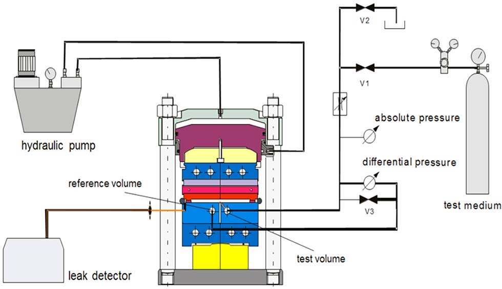
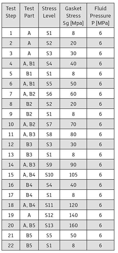
The test method consists of analyzing data from multiple gasket leakage tests in order to calculate the three aforementioned design constants for a particular model and size of gasket. The testing can be performed in a pair of appropriately sized flanges, using bolts to achieve varying gasket loads, or in a servo-hydraulic test stand of adequate capacity (Image 1).
In total, the procedure consists of two high-pressure (HP) tests at 6 megapascal (MPa) (870 pounds per square inch [psi]) of helium and two low-pressure (LP) tests at 2 MPa (290 psi) of helium, for a total of four tests on four different specimens. In addition to the differences in internal pressure, the HP and LP tests are also distinct from each other in terms of the gasket loading sequences.
The HP test consists of loading and unloading sequences, continually introducing successively higher loads onto the gasket while interrupting this loading sequence with intermittent unloading ramps. The LP test consists of only a loading sequence.
In both tests, the helium leak rate is measured at these various gasket loads.
For the purposes of test evaluation and gasket constant derivation, the different loading sequences of the tests are categorized as either Part A or Part B. Part A consists of the loading sequences, while Part B consists of the unloading sequences. Therefore, the HP test contains both Part A and Part B sequences, while the LP test consists of Part A only.

See Image 2 and Image 3 for details of the HP and LP testing sequences, respectively.
With its increasing gasket loads, Part A simulates assembly of the gasket in the joint, and therefore represents the gasket seating process. The data from this portion of the test is used to determine the required seating load for the gasket to create a tight seal.
Part B simulates the operating conditions by unloading the specimen to different gasket stress levels. This replicates unloading of the gasket, seen in real applications, due to various factors including internal pressure and relaxation effects of a gasket during operation. Part B test data is used to determine the required operating gasket load in order to maintain a tight seal.
Results Analysis & Gasket Characteristic Calculation
After the four tests (two HP tests and two LP tests) have been completed, a verification procedure—known as a validity check—must be performed to check whether the measured helium leakage at individual gasket stresses demonstrates satisfactory repeatability within the high-pressure and low-pressure test pairs.
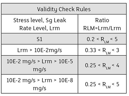
The leakage (expressed in milligrams/second [mg/s] of helium) of corresponding steps in the high-pressure and low-pressure tests are directly compared by dividing the leak rate of the first test of the pair (Lrm1) by the leak rate of the second test of the pair (Lrm2) to produce a ratio: RLM. The data is considered validated if the value of RLM falls within the bands described in Image 4 for each corresponding test step.
Where:
P = Fluid pressure (MPa),
P* = reference pressure (0.1013 MPa),
Lrm = mass leak rate (mg/s) of ROTT gasket specimens dimension;
Lrm* = unit mass leak rate (1 mg/s for a 150 mm gasket OD)
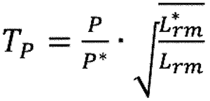
Equation 1
Once acceptable repeatability between the test pairs is realized, the gasket constants a, Gb and Gs may be calculated. The source of these values can be visualized on a combined plot of gasket stress versus the tightness parameter (an expression of leakage, see Equation 1) on log scales for all four tests (Image 5).
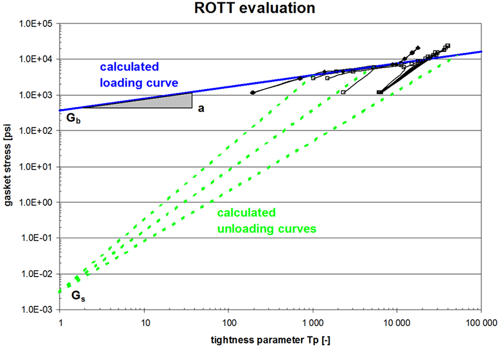
Gb and a are characteristics of the regression of the Part A data set that delivers the highest value of R2 (least square method).
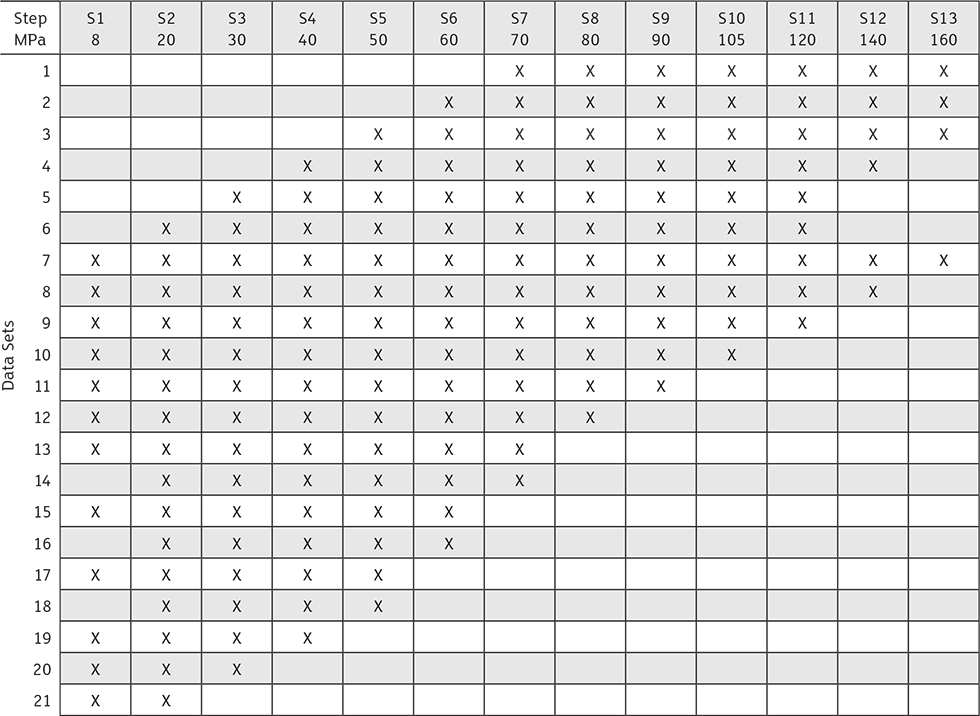
There are 21 possible sets of Part A data defined by the standard that must be evaluated (Image 6).
After the data set whose regression returns of the highest value of R2, Gb is found as the intercept of this regression line at Tp = 1, while a is the slope of this line (Image 5).
The determination of the unloading constant Gs is more straightforward compared to the other two constants. Gs is defined as the stress intercept at Tp = 1 associated with the regressions of each unloading sequence of the Part B data set (Image 5).
The standard practice ASTM F2836-18, or ROTT, is the newest publication by a standardization body in the U.S. aimed at producing gasket constants to be used in the design of gasketed BFJs. The loading and unloading gasket stress sequences, combined with leakage testing at different internal pressures, create gasket constants that can characterize a gasket’s performance over a broad range of installation and service conditions.
Industry is already demanding these constants for gasket products while awaiting the publication of the design equations as determined by the ASME BPVC Section VIII Special Working Group.
The original article was featured on pumpandsystems.com and was written by Adam Arnett. Adam is the engineering project manager at amtec North America, where he is responsible for testing and analysis projects of fluid sealing technologies according to industry standards and custom investigation and testing projects.
For more information about ASTM guidelines or gaskets and bolted flanges, contact Gallagher Fluid Seals.