This article is the third of a three-part series, focusing on common fluid power products, along with a description of the sealing systems that are typically used in those products. Part 1 and Part 2 on our blog, or you can download the entire Fluid Power Application White Paper by clicking on the image below.

In a fluid power system, piston-type accumulators are used to store pressurized fluid for use when additional fluid volume is required. As shown in Figure 9, a wide floating piston separates a compressible gas from a liquid. In this example, pressurized gas is located on the cavity side of the piston. A floating piston also allows for pressure fluctuation in the system.
Low friction is not necessarily a design objective in selecting a seal. Squeeze seals, which offer improved low pressure sealing, are desired so long as they provide smooth travel with low wear. If a bi-directional seal is used, additional space is made available for a wider wear ring. The wear ring should be located on the lubricated side of the piston. To help prevent contamination that can damage the seals or increase wear, accumulators should be mounted in the vertical position.
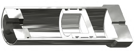
Energy Absorbing Cylinder
Concentric double walls provide both the transfer channel and space for gas “spring” to accommodate the differential volumes in opposite ends of this energy absorbing design. When a moving mass engages the large rod, it drives the piston against the coil spring. 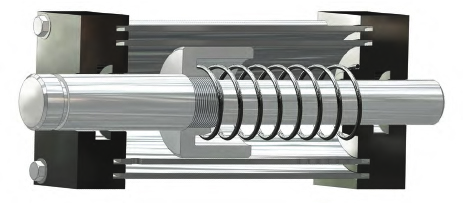
Some versions of this design utilize a piston seal facing the spring-end of the cylinder, but the shock loading on impact can twist the seal in its groove and set up a high-probability extrusion situation. Where severe impacts are anticipated, choose seals for their high stability and ensure the seal does not travel over the orifice ports.
The return stroke is usually provided by the compressed spring alone. In this design, the return stroke will be slow since the flow must pass through the same fixed orifices in the reverse direction with only the spring energy to drive it. In other designs, the load may also power the return stroke.
High Shock Energy Absorbing Cylinder
Where it is possible to use an external hydraulic accumulator or connect into a hydraulic system with its own accumulator, a ram-type, energy absorbing cylinder may be safer and easier to regulate than the previous design (shown in Figure 10). This design utilizes a snug-fitting ram to isolate the rod seal from shock pressures developed on the ram face. Note that any leakage past the snug-fitting ram will bleed off through the oil return passage with fluid from the orifice plugs. As shown in Figure 11, only a single rod seal is required. A wide variety of rod seals could be used in this application with the principal deciding factors being the pressure range of the connected hydraulic accumulator, and the friction at the rod and seal interface.
Most dynamic applications require a hard running surface on the dynamic portion of the hardware. The harder surface allows the use of higher reinforced seal materials that will increase both the seal and hardware life.
Softer running surfaces must use lower wear resistant seal materials that will not damage the hardware, but normally yield shorter seal life. A balance between seal material and dynamic surface hardness must be met to ensure that the seal remains the sacrificial component.
When the dynamic surface hardness is below 45 Rc, most seal materials will polish the running surface of the hardware and the seal. This initial break-in period will cause seal wear to taper off over a period of time depending on the seal material, surface finish, pressure and velocity of the application. When hardness exceeds 45 Rc, the initial surface finish is very important since the surface is much harder to polish and the time to achieve break-in is longer. Surface hardness above 65 Rc will resist polishing and therefore the initial surface finish is more critical to seal life.
The hardness of the dynamic hardware surface affects the wear rate of the seal. Additionally, some seal jacket materials are abrasive and will wear softer metal shafts or dynamic components. In general, higher surface hardness results in better overall seal and hardware performance. The ideal hardness of the dynamic surfaces of the hardware is 50 to 60 Rockwell C.
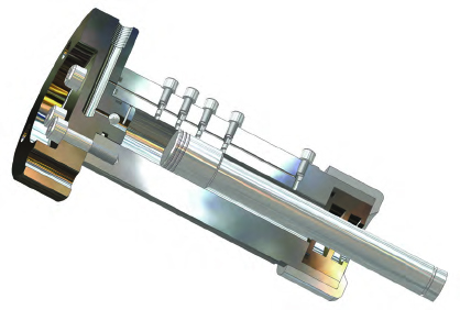
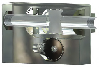
Linear to Rotary Motion Converter
A linear-to-rotary motion converter is a rack and pinion type design that utilizes a fluid power linear actuator to drive rotary motion. As shown in Figure 12 the rod and piston are fixed, while the cylinder bore and end glands move in reciprocating motion. A toothed rack engages a pinion gear, which rotates as the cylinder strokes.
Please contact us with any questions regarding Fluid Power Applications and how we can help seal your fluid power systems.