Attention: When installing GORE Gasket Tape Series 1000 in joints with multiple (2 or more) gaskets compressed with a single set of bolts or clamps, see the installation supplement “Installation on Joints with Multiple Gaskets,” for additional mandatory instructions.
1. Select the size
GASKET WIDTH
Select the gasket width that provides enough material to align the gasket tape flush with the inner and outer diameter. Ensure full coverage of the glass surface. Excess material may exceed the outer diameter.
GASKET THICKNESS
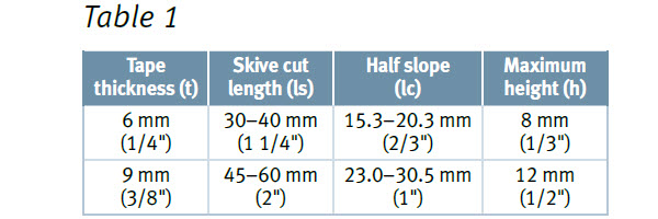
Most applications require a base layer of 6 mm (1/4") tape, which can accommodate deviation up to 1.5 mm (1/16") without shimming. Applications with deviation up to 2.3 mm (0.090") can utilize 9 mm (3/8") tape without shimming.
SHIMMING
To effectively seal flanges with deviations beyond the maximum for the base layer, a shimming process is recommended. Use of 3 mm (1/8") GORE® Series 1000 shim tape as a shim layer will accommodate an additional 1.5 mm ( 1/16") of flange deviation. Ensure the shim layer has the same width as the base layer.
2. Determine a Torque Value
To achieve a reliable seal, adequate gasket stress must be applied during installation.
Typical minimum stress to seal values for GORE Gasket Tape Series 1000 are:
6 mm (1/4"): 14 MPa (2,030 psi)
9 mm (3/8"): 18 MPa (2,610 psi)
Perform an engineering calculation to determine the torque value for your specific application.
Industry guidance is available, for example in ASME PCC-1 Guidelines for Pressure Boundary Bolted Flange Joint Assembly, and EN 1591-1 Flanges and their Joints - Design Rules for Gasketed Circular Flange Connections - Part 1: Calculation.
However, ASME PCC-1 does not include glass-lined steel specialties. Therefore, it is advised to contact the equipment manufacturer for an adequate torque recommendation.
3. Install the Gasket Tape
A. Prepare the Flange
Open the flanges a minimum of 15 cm (6"). Ensure the flanges are well secured for a safe working environment.
Completely clean the surface to ensure optimal adhesion.
Remove all oil, graphite, and other residue.
B. Measure Flange Irregularities
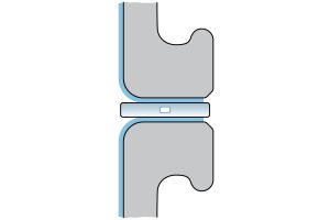
Place a separator between the flanges to avoid glass-to-glass contact (e.g. fiber sheet or plywood board)
Close and align the flanges without compressive load beyond equipment weight.
Use a thickness gauge to measure the irregularities or flange deviations.
Mark all irregularities and their magnitude on the flange for later reference.
Be sure to mark the flange orientation for future flange alignment.
C. Perform Initial Skive Cut
Unwind about 0.5 m (1.5 ft) of GORE® Gasket Tape Series 1000. Cut the end with a sharp knife on a clean, firm surface using the skiving technique.
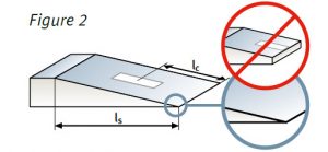
The length of the skive cut, ls, should match the dimension in table 1. The skive angle is < 10°.
ATTENTION: It is critical that the skive runs out smoothly, avoiding any step. Be sure to use proper protective gloves when using a knife.
D. Apply Base Layer of Gasket Tape
Position the skived end of the gasket tape at a location where no shimming is needed, thus at a place where both flanges touch (see 2.3). Begin near the designated starting clamp or bolt.
Remove the adhesive backing as it is installed, to prevent the the adhesive strip from picking up dirt during the installation.
ATTENTION: The adhesive on GORE Gasket Tape Series 1000 adheres best to clean surfaces. In cold conditions, gently warm the gasket tape before installation.
E. Complete the Layer of Gasket Tape
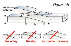
Complete the gasket by laying the tape over the skived end, extending beyond ~15 mm (1/2"). To prepare for the second and final skive cut, identify and mark the starting and end points.
Cut away the gasket material at an angle, so that the maximum height, h, matches the dimension in table 1. This will leave the tallest section of the skive ~1/3 thicker than the original gasket.
F. Shim Flange Irregularities
Using the measurements performed in Step B, use the 3 mm (1/8") GORE® Series 1000 shim tape to perform the following shimming process.
Measure the length of the irregularity to be shimmed.
Cut the gasket tape approximately 4 cm (1 1/2") longer than the measurement.
Cut both ends of the gasket tape shim using the skiving technique described in Step C.
Place the gasket tape shim on the previous layer of GORE® Gasket Tape Series 1000.
Repeat steps a) through d) until the number of shims have been installed for the measured irregularity.
ESA / FSA Gasket Installation Procedures Assuring Joint Integrity and Maximum Safety
ASME PCC-1 Guidelines for Pressure Boundary Bolted Flange Joint Assembly
VDI 2200 - Tight flange connections: Selection, calculation, design and assembly of bolted flange connections
However, extra care during assembly and bolt-up is advised with glass-lined steel equipment. The above guidelines do not take into account the specialties of the glass lining.
FOR INDUSTRIAL USE ONLY
Not for use in food, drug, cosmetic or medical device manufacturing, processing, or packaging operations.
Gallagher Fluid Seals is an authorized Gore distributor. For more information about Gore products, contact us today.