Original content can be found on Parker’s Website and was written by Nathan Wells, application engineer, Engineered Polymer Systems Division.
So, you’ve unboxed the shiny new Parker seals you ordered – now what? Installing seals for the first time can be challenging without the right know-how and tools. In this article we’ll discuss best practices for seal installation in linear fluid power systems, and how to design your system to make seal installation fast and damage-free.
SEAL GROOVE STYLES
First, let’s look at three common groove styles:
• Closed
• Stepped, and
• Open (or two-piece)
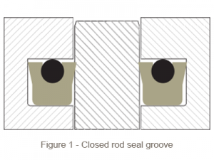
Closed groove
The closed seal groove fully encapsulates the seal and is the most common style used (see Figure 1).
Closed grooves are simple to machine and offer the best support for seals. Since seals in this configuration are surrounded by solid metal, without a well-developed process, installation can be challenging. Rod seals need to be folded to fit into internal (throat) grooves and piston seals must be stretched over the outside of the piston.
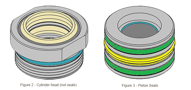
Notice how both designs shown in Fig. 2 and Fig. 3 utilize static seals (turquoise colored seal) on the opposing side of the dynamic, primary seals. Therefore, installation in either instance requires techniques and tools for both rod and piston seals.
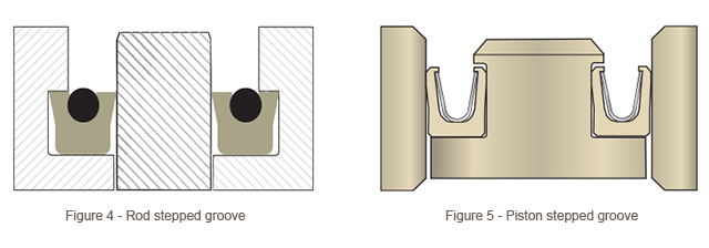
Stepped groove
Typically utilized to ease seal installation, stepped grooves feature a reduced diameter on the low-pressure side of the seal as shown in Fig. 4 and Fig. 5.
As shown, the “step” is just wide enough to hold the seal in place as the rod or piston strokes back and forth. This way, seals don’t have to be folded or stretched nearly as much when installing. This design works well for single seals only holding pressure from one direction, like Parker FlexiSeals™.
When using multiple seals stacked in series or in systems with bi-directional pressure, a closed or two-piece groove is needed for support on both sides.
Open and two-piece grooves
Open or two-piece grooves are used when the seal is either too small to be stretched or folded into a closed groove, or if it’s made of a material that doesn’t spring back after flexing.
Figures 6 and 7 show two examples of open grooves. Figure 6 uses a washer and a snap ring to hold the seal in place. Figure 7 uses a bolt-on cap. These groove designs can be used for bi-directional seals, too. As you can see, open grooves cost more to produce but seal installation is a snap.
Open grooves also make removing the seal much easier – useful in systems which require periodic seal replacement.
INSTALLATION METHODS AND TOOLING
Installing seals with your bare hands is tough! Parker has several tips and tricks you can use to ease the process. For large scale production, building a set of custom tools or even designing a fully automated setup will save time and reduce labor.
Seal material considerations
Different installation tactics are required for the diverse range of seals Parker manufactures. Polyurethane and rubber seals are extremely resilient and won’t be damaged by stretching or folding. Cylinder components made from hard plastics are less flexible. Parker FlexiSeals incorporate a metal spring inside of a thin PTFE jacket, so stretching or folding should be avoided. If a PTFE seal must be installed in a difficult location, Parker offers “cap seal” designs which are energized by an O-ring and are robust enough to handle deformation during installation. Installation speed is key in these cases. Testing has shown that when PTFE rings are swiftly stretched over a piston (less than a second), they recover closest to the original diameter, whereas seals stretched slowly need a re-sizing tool passed over the seal to aid recovery.
Hard plastic components like PEEK backups and Nylon wear bands are supplied with splits to aid installation. Split rings can be collapsed to a smaller diameter to snap inside a cylinder head, or opened to snap over a piston. Since these secondary components aren’t doing the sealing, there’s no concern with the split causing a leak.
Installing Rod Seals
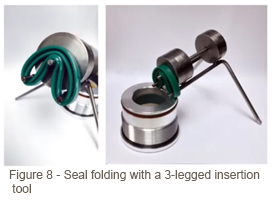
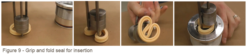
For low volume production on rod sizes above 2”, hand-folding each rod seal into the groove can work. For smaller sizes where a hand won’t fit, do yourself a favor and order (or make) a 3-legged rod seal installation tool (see Fig. 8).
These tools grip and fold the seal for insertion, which is especially useful in deep cylinder heads housing several seals in a row (see Fig. 9).
There are many online vendors who sell rod seal installation tools. If you need help, Gallagher Fluid Seals has some recommendations.
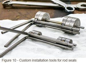
The two tools pictured in Figure 10 were made for use in Parker's lab. Multiple sizes are needed for different rod diameters.
The size of the rod seal will dictate the method of installation. Seals with larger cross-sections are more robust, but harder to fold into place. Small diameter cylinder heads don’t leave much room for installation. For closed grooves, this is the rule of thumb: the rod diameter needs to be 5 times larger than the cross-section. By following this rule, Parker's smallest 1/8" cross-section BD, BT, and PolyPak rod seals will require open grooves when rod diameters are smaller than 5/8".
Installing piston seals
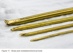
Piston seals are less challenging, purely because you’re not confined to a small space while installing. The simplest method for stretching seals into a groove is to hook one side over the piston, and then use a piece of non-scratching brass (see Fig. 11) or plastic bar stock to gently pry the seal over the other side.
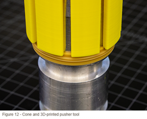
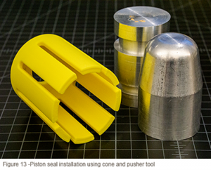
While simple, the above method can pinch or unevenly stretch the seal, causing it to leak. For an upgrade, machine a cone and pusher tool out of aluminum and plastic, respectively (see Fig. 11). These are especially convenient for stretching large seals because an arbor press or mallet can be used for additional force. While pushing, the flexible fingers of the tool ensure the seal is being evenly stretched over the piston. PTFE cap seals in particular will be damaged by “necking” caused by uneven stretching.
Since some tools are only used for low volume testing, 3D-printed pushers work great. For production-grade tooling, cut pushers from a tough plastic billet like Nylon.
OTHER CONSIDERATIONS
In addition to gently coercing seals into place, there are other elements of the assembly process to consider. Often overlooked, poor cleanliness of the work area can break an otherwise good procedure. Dirt and metal shavings present in manufacturing areas can become trapped in a cylinder. Over time, they will abrade the seal lip and scratch expensive polished metal sealing surfaces, leading to premature leaking.
Additionally, ensure hardware is deburred beforehand so the seals don’t get cut by a sharp corner. Our catalog recommends a light break (0.005” max) on groove corners to prevent cutting the seals, and – from personal experience – also the hands of the assembler. Larger breaks are fine in areas which aren’t supporting a seal (e.g. the outside of a cylinder head). If smoothing a corner or installing from another direction is not an option, like in some ultra-high-pressure systems, mask sharp surfaces with tape or a plastic sleeve before passing the seal over it. This method is also highly recommended when passing seals over threads.
Even when using an installation cone or protective sleeve, lubricating the seals and hardware beforehand with system fluid or a compatible grease prevents damage and helps the seals slide into place. For stiffer, higher durometer seal materials like Resilon® and PolyMyte®, heating seals in an oven or hot fluid bath will temporarily soften them, making them easier to fold or stretch (be sure to use system-compatible fluid). Soaking for thirty minutes at 200°F is within the max temperature rating of most seal materials and isn’t too hot to handle with bare hands.
Some installation headaches can also be overcome with clever system design. Generous chamfers on the ends of the rod and bore help gently compress seals when the piston or rod is inserted. This also keeps the seal lips from getting caught on a corner and folding, thus ruining the seal. Switching to a bi-directional seal will eliminate problems with seals being installed upside-down (nobody likes to admit it, but this happens).
CONCLUSION
Be smart and safe when installing seals. Buy or create tools to do the hard work for you. If leaks are happening right after assembly, consider the installation process suspect.