We begin with two-piece glands. Spring energized PTFE seals are rigid when compared to elastomer seals such as O-rings, and can be damaged if stretched or compressed beyond their material limitations.
That’s why we recommend using a two-piece, split gland design whenever possible. This allows easy installation or removal of the spring energized PTFE seal without the need for additional tools, and will greatly reduce the risk of damage to the seal.
Lead-in chamfers that are blended and very smooth are needed to prevent seal damage during installation. You can find full surface finish recommendations by downloading our complete spring-energized seal guide.
Heal First Seal Installation
When installing the spring energized PTFE seal with the heel or non-pressure side first, the lead-in chamfers may be smaller than when the seal must go in lips first. The spring energized PTFE seal is designed with a slight clearance at the heel, and is also chamfered.
If lead-in chamfer angles cannot be made, a full polished radius may also be used. Both designs must be very smooth and free from sharp edges that can damage the seal.
Note: Sometimes a combination of heel first and lip first installation is needed. In these situations, match the appropriate table with the demands made on the chamfer. You’ll find the table below.
Lip First Seal Installation
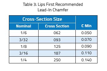
When installing the spring energized PTFE seal with the lips or pressure-side first, the lead-in chamfers need to be longer than when the seal goes in heel first. The seal is designed with pre-load interference on the lips that require additional clearance to prevent damage during installation. A stepped retention plate is required to provide a flat-backed surface for the seal and to prevent extrusion into the lead-in angles. All chamfers must be very smooth and free of sharp edges that can damage the seal. Use installation tools if the necessary angles and retention plate cannot be achieved.
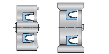
Two-Piece Flanged Glands
The flanged design can be used in either static, rotary or reciprocating applications and is designed to be dynamic only on the ID. It excels in rotary applications because the flange can be clamped axially to prevent the seal from rotating with the shaft. This added stability allows the flanged design to hold more pressure at higher surface speeds. The gland must be made in two pieces for installation purposes and could be lips-first or heel-first. Use the tables below for the chamfer commensurate with the direction of shaft insertion.
Step Cut Glands
This solid one-piece configuration offers an alternative to the two-piece gland. It has a reduced wall on the pressure side of the groove, which allows the seal to snap into the groove without the need for a separate retainer or installation tools.
The step is designed to hold the seal in the groove during final assembly and under dynamic conditions such as low pressure return strokes in reciprocating applications. In pressurized conditions, the spring energized PTFE seal is naturally held into the back of the groove.
The step cut gland can be used for both rod and piston seals. We recommend a spring energized PTFE seal with a scraper lip on the static surface to provide a more positive snap-tight fit.
Step Cut Gland Installation
Step cut glands can only be used when the seal sees pressure from the open or spring side of the seal. This requires the seal to be installed heel or non-pressure side first, snapping the seal lips behind the retention step. After installing the seal into the groove, the assembly can be pushed into a piston bore, or over a rod.
Alternative Glands
For heel first installation with a snap ring retainer, the snap ring groove is set into a reduced diameter to ensure that the seal does not pass over the edges. This design can be used for both rod and piston seals. For lips first installation with a support ring and snap ring retainer, the snap-ring groove is at a reduced diameter to prevent damage to the seal. The support ring must meet clearance gap recommendations as outlined in this guide. Load ratings for snap rings must be considered to prevent fatigue or failure.
For more on glands and gland installation, including closed glands, be sure to download Gallagher Fluid Seals’ spring-energized seal guide.