The Garlock Family of Companies has launched a new fully-coated isolation gasket known as EVOLUTION.
EVOLUTION® Isolation Gaskets
The next generation of isolation gaskets, EVOLUTION®, features easier installation, tight sealing, high-temperature operation, no permeation, hydrotesting isolation, fire-safety and chemical-resistance.
Featuring a thinner, 1/8-inch design, EVOLUTION minimizes the difficulties encountered when attempting to install thicker isolating gaskets. The full-coating encapsulation allows the gasket to be hydrotested and left in the pipeline with the same isolation properties as before it was tested.
EVOLUTION's coating is highly resistant to abrasion and impact while providing chemical resistance to hydrogen sulphide (H2S), steam, carbon monoxide, carbon dioxide and other chemicals often found in oil and gas pipelines. This fully encapsulated coating also prevents the need for expensive exotic cores, as it eliminates contact to exposed metal.
In addition to KLINGER's complete Sheet Gasketing Product Line which now includes the new major change in construction of their PTFE Products TC 1003, TC 1005, and TC1006, they have added a great new product to cover additional applications during day-to-day operation.
The KLINGER SAVER
A new product we are featuring on our blog is THE KLINGER-SAVER - a tool to eliminate hand injuries.
Bolt tightening or loosening activities, or using slug wrenches and hammers can often the cause of serious finger or hand injuries.
The KLINGER-SAVER is a safety device that allows an assembly technician to remove his hand from the potential danger of being struck by the hammer.
The American Society for Testing and Materials (ASTM) International Committee F03 on Gaskets recently released the latest standard practice to derive gasket design constants for the proper design of bolted flanged joints (BFJs): ASTM F2836-18. End users of gaskets can then use these gasket constants for proper BFJ design using calculation methods that are currently being developed by a special working group of American Society of Mechanical Engineers (ASME) Boiler and Pressure Vessel Code (BPVC) Section VIII at the time of this publication. In this article, the current test procedure, the mathematical models of the test evaluation and the calculation of the characteristics are described and discussed.
IMAGE 1: Example of a servo-hydraulic test stand (Images courtesy of Amtec North America, Inc.)
Background
Most industry professionals are aware that BFJs used in fluid service are complex mechanical systems. In order to create a high-performing BFJ, a designer needs to carefully consider not only the service conditions the BFJ will encounter, but also the performance characteristics inherent to the components of the BFJ. The gasket itself is one of these critical, yet often overlooked, components, and efforts to determine and quantify the performance characteristics of gaskets have been ongoing for decades.
The newest of these efforts to be published in the United States is ASTM F2836-18: Standard Practice for Gasket Constants for Bolted Joint Design (commonly referred to as the Room Temperature Tightness Test, or ROTT). The design constants produced by this method enable a more robust design of BFJs compared to previous, antiquated design constants, such as the m and y factors.
The crucial gasket constants produced by this standard practice are a, Gb and Gs. These constants effectively describe the tightness behavior of the gasket material, reflective of different loading and service conditions.
In addition to their application to the ASME calculation method currently under development, the constants can also be used to compare materials so the proper one may be selected for the application.
IMAGE 2: High-pressure test sequence
Who Will Use ASTM F2836-18?
ASTM F2836-18 is a helium leakage testing and evaluation method that determines tightness-based design constants at room temperature for pressurized bolted flange connections that are designed in accordance with ASME BPVC. As such, ROTT applies mainly to all types of circular gasket products—including, but not limited to, sheet-type, spiral wound, solid metal and jacketed gaskets.
As such, these constants stand to be of interest to all parties who work with circular gaskets and have a vested interest in producing a high-performing BFJ, including end users, BFJ assembly contractors and gasket manufacturers.
Testing Procedure
The test method consists of analyzing data from multiple gasket leakage tests in order to calculate the three aforementioned design constants for a particular model and size of gasket. The testing can be performed in a pair of appropriately sized flanges, using bolts to achieve varying gasket loads, or in a servo-hydraulic test stand of adequate capacity (Image 1).
In total, the procedure consists of two high-pressure (HP) tests at 6 megapascal (MPa) (870 pounds per square inch [psi]) of helium and two low-pressure (LP) tests at 2 MPa (290 psi) of helium, for a total of four tests on four different specimens. In addition to the differences in internal pressure, the HP and LP tests are also distinct from each other in terms of the gasket loading sequences.
The HP test consists of loading and unloading sequences, continually introducing successively higher loads onto the gasket while interrupting this loading sequence with intermittent unloading ramps. The LP test consists of only a loading sequence.
In both tests, the helium leak rate is measured at these various gasket loads.
For the purposes of test evaluation and gasket constant derivation, the different loading sequences of the tests are categorized as either Part A or Part B. Part A consists of the loading sequences, while Part B consists of the unloading sequences. Therefore, the HP test contains both Part A and Part B sequences, while the LP test consists of Part A only.
IMAGE 3: LP test sequence
See Image 2 and Image 3 for details of the HP and LP testing sequences, respectively.
With its increasing gasket loads, Part A simulates assembly of the gasket in the joint, and therefore represents the gasket seating process. The data from this portion of the test is used to determine the required seating load for the gasket to create a tight seal.
Part B simulates the operating conditions by unloading the specimen to different gasket stress levels. This replicates unloading of the gasket, seen in real applications, due to various factors including internal pressure and relaxation effects of a gasket during operation. Part B test data is used to determine the required operating gasket load in order to maintain a tight seal.
How this feature can improve performance and efficiency with gaskets
Gaskets have always been part of industrial production. However, gaskets have not always been forgiving, easy to use or simple to remove. What if the sealing products were designed to optimize the work put into them? What if the design had a level of intelligence built in? What if the design could make up for equipment damage? When used properly, enhanced surface profiles for gaskets can reduce leaks, spills and other releases that can damage the environment, put people at risk, result in fines and lead to costly downtime.
Using surface profiling to reduce area and increase stress is found in everyday life, from the soles of running shoes to the treads on vehicle tires. Reducing the contact area while maintaining compressive force results in increased stress. In the case of gaskets, traction or friction between a gasket and the flange faces is critical to holding internal pressure. If the downward force created by the fasteners in a flange is diluted or spread over a larger area, the overall stress is reduced.
Compressibility
Adding raised features to the surface of a gasket to reduce contact area and increase stress also tends to impact compressibility. Compressibility represents the ability of the gasket to conform to the surfaces it is being used to seal. Flange surfaces usually show signs of wear, pitting, scratches or other defects. It is cost-prohibitive to make two mating flange faces smooth and flat enough to seal without a gasket. The more compressible a gasket is, the better chance the user has of attaining an effective seal.
Image 1. (clockwise left to right) Traditional material sees heavier load around the gasket bolts and lighter load farther from the bolts. Image 2. Load distributed more evenly. Image 3. More stress toward the bolts. Image 4. Stress spread evenly around the gasket. (Images courtesy of Garlock)
Pressure Resistance
Compressibility also impacts the amount of pressure exposure on the gasket. When a flange assembly is pressurized, the internal media pushes outward on the inner diameter of the gasket. The thinner a gasket becomes, the less outward force it sees from internal pressure. This is referred to as improved “blowout resistance.” Unfortunately, one common error made when a gasket blows out is to replace it with a thicker gasket. This puts more gasket surface in the pipe or vessel for the internal pressure to act on.
Sealability
To create an effective seal, there are two functions the gasket must accomplish.
First, it needs to conform to the flange face to prevent the media from passing between itself and the flange faces. This is where the compressibility is important.
Have you ever received the dreaded 2 a.m. call from plant staff saying that things are at a standstill – production is down?
You arrive at the plant, walk through the parking lot, coffee in hand, and head to the locker room. When you come out on to the plant floor, there are several people staring at you with a look of panic on their faces as steam or process chemical sprays from a pipe flange.
Prognosis……gasket blowout.
You think to yourself “didn’t we just replace that gasket?”, or perhaps “we should have replaced it during the last shutdown but chose not to because of time constraints or cost cutting.”
If this scenario is new to you, you are lucky and you can go back to sleep… the 2 a.m. call was a wrong number. If it’s not new to you, this means you are most likely a Plant Supervisor, Maintenance Manager or Plant Personnel in some capacity.
Roll up your sleeves, grab your torque wrench and let’s get to work!
Gasket Lifespan
If I had a nickel for every time someone asked me, “How long will my gasket last?” I would be a rich man. As you can probably guess, “How long will my gasket last?” is a loaded question to which the practical, factual, and political answer is… an Application Engineer’s nightmare!
A gasket may last 5 years, or it could last 20 years. I cannot give you an exact date or lifespan of a gasket; however I can give you some insight into factors that will give your gasket the best chance at a long and prosperous life between the flanges.
Replacing Aging Water Infrastructure With NSF Compliant Materials
There are over 155,000 public water systems in the United States and more than 286 million Americans who rely on community water systems daily. Since most of the infrastructure was built between the early 1900's and 1960 using outdated technology/products and capabilities, nearly everything is approaching the natural end of it's lifespan.
Some estimates put the repairs and replacement of the infrastructure between $250B and $500B over the next 20-30 years. Several applications will need to be updated or fully replaced for the safety of consumers and quality of delivery, including:
Food and beverage producers rely on a wide array of equipment to ensure their products are safe and free of contamination. Sealing devices such as gaskets are key components in this equipment, yet do not receive the attention they warrant given the critical importance of their function.
PTFE (Polytetrafluoroethylene) Molecule
PTFE-based and elastomeric seals have for decades been the products of choice for food and beverage applications. The two most commonly referenced Food and Drug Administration (FDA) standards for sealing products are found in the Code of Federal Regulations under Title 21 (Food and Drugs), part 177 (Indirect Food Additives: Polymers). Section 177.1550 focuses on perfluorocarbons such as PTFE- based products, and Section 177.2600 deals with rubber articles intended for repeated use.
These two standards specify which ingredients used in the production of sealing products are acceptable for applications where contact with food products can occur, as well as how much of the approved ingredients can be released from the polymer/elastomer when extracted with specific media — i.e. water, hexane, etc. — under specified testing conditions.
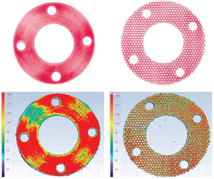
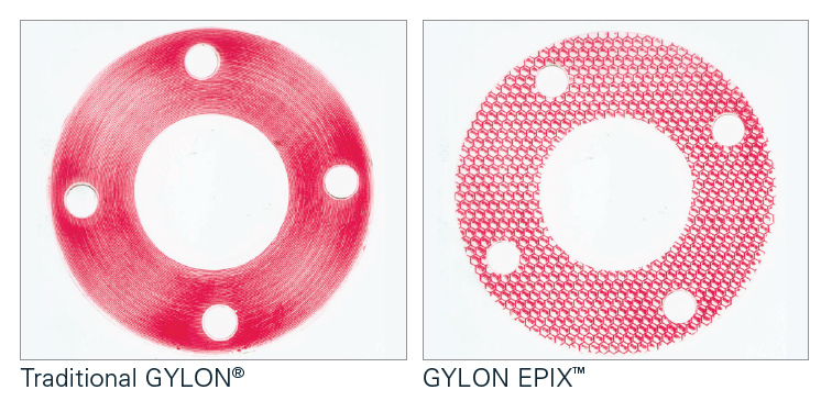
GYLON EPIX™ is a newly developed family of PTFE gaskets. It is manufactured using a patented, profiled surface based on our proven Fawn, Off-White, and Blue GYLON® to create highly conformable materials for optimum sealing performance.
THE EPIX™ DIFFERENCE
GYLON EPIX™ and a traditional full face gasket were installed in a 3”-150# flat face flange at 120 ft.lbs. with pressure sensitive film. The film revealed that the traditional material saw heavier loading-near and around the bolts, and lighter loading at the points furthest from the bolts. The GYLON EPIX™ was able to distribute the load more evenly and prevent the low loading phenomenon.
The pressure sensitive film was then analyzed with special software that translate the various shades of red into a full color spectrum that provides a better visualization of the stresses that were developed on each of the gaskets. Again, while the traditional gasket saw areas of lower stress (green and blue areas), the hexagonal pattern in the GYLON EPIX™ concentrated and distributed the stress more evenly across the entire gasket.
GYLON EPIX™ is a family of gaskets that effectively seals a broader range of applications and is more forgiving during the installation process. It allows the end user to save valuable turn-around time, reduce re-work, and lower costs, helping them to finish ahead of schedule and under budget.
GYLON EPIX™ features a hexagonal surface profile that provides the torque retention and blowout resistance of a thin gasket and the conformability of a thicker gasket. GYLON EPIX™ Style 3504 EPX is a high performance, aluminosilicate microsphere filled PTFE sheet material designed for use in moderate concentrations of acids, and caustics, as well as hydrocarbons, refrigerants, and more.
INDUSTRY
Mining
CUSTOMER
Copper Mine
BACKGROUND
Customer reported problems with continuous leaks that required ongoing maintenance and attention taking manpower and resources away from other critical operations for the plant.
Sealex® joint sealant, specially processed, 100% pure PTFE on a roll, provides soft, highly compressible gasketing for longer life and trouble-free sealing. Its form-in-place versatility also cuts maintenance and storage costs. The high compressibility of Sealex® enables it to effectively fill flange imperfections for a tight, leak-free seal. Under pressure, it provides a very wide, thin ribbon-like joint sealant. Unlike conventional PTFE which is prone to cold flow, Sealex® has good creep resistance and bolt torque retention properties.
Sealex® joint sealant does not support bacterial growth or cause product contamination and is FDA compliant. It has virtually no shelf-life concerns since PTFE is unaffected by normal environmental conditions.
It has excellent resistance properties to chemical attack. It is ideal for most chemical services at temperatures to 500°F (260°C) and pressure to 2,000 psi (138 bar). It is also suitable for cryogenic use to -321°F (-196°C).