Garlock
- September 10, 2019
The search for the ideal Polytetrafluoroethylene (PTFE) gasket has been elusive. Competing applications and workplace variables have led to the creation of myriad solutions, yet none that has proven fully adaptable and appropriate for universal adoption.
Garlock Sealing Technologies considered this to be a critical yet entirely solvable shortcoming. And it is against this backdrop that in 2016, they set out to compile a comprehensive list of attributes for the ideal PTFE gasket — a wish list, as it were — in order to build a better gasket.
Working with a third-party survey development company, Garlock developed an exhaustive questionnaire that probed every aspect and functionality of PTFE gaskets, testing and adjusting the questions until they had a workable, finalized version.
Using this final questionnaire, Garlock conducted extensive interviews at 15 major chemical processor companies, speaking with 20 engineers responsible for process operations, projects, maintenance and reliability. The goal was simple: to discover the ideal characteristics and their relative importance that engineers sought in a PTFE gasket.
After several months of data collection, Garlock analyzed the feedback and noted the most popular responses:
- 28% of respondents said that they struggled with how different gaskets required different compressive loads and how to ensure that those gaskets had been installed properly
- 21% expressed frustration with the creep properties of PTFE gaskets
- 21% desired a gasket that seals with less compressive load
- 14% expressed frustration at the installation inconsistencies of their fitters
- 14% expressed frustration with leaking, especially after a successful installation and start-up
From those answers, Garlock drew the following conclusions, representing the most desirable and essential PTFE gasket characteristics:
- Seal: Seals easily
- Installation and assembly: Forgiving of poor installation or assembly practices
- Forgiving: Forgiving of poor flange conditions
- Retention: Maintains a seal after installation
- Flexible: Can be used in a broad range of services to avoid user confusion and reduce inventory
Introducing: GYLON EPIX
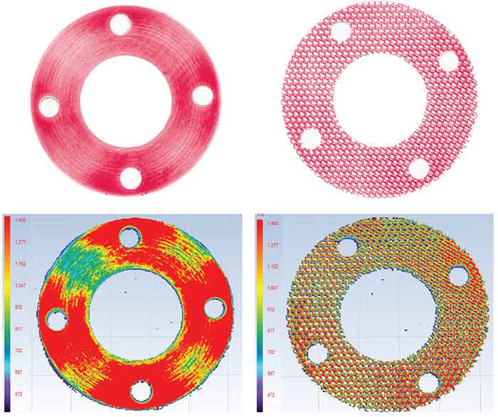
Garlock used this feedback in developing a next generation PTFE gasket — GYLON EPIX. Featuring a hexagonal surface profile, GYLON EPIX offers superior compressibility and sealing for use in chemical processing environments. Its enhanced surface profile performs as well or better than existing 1/16″ or 1/8″ gaskets, allowing end-users and distributors to consolidate inventory, lower the risk of using incorrect gasket thicknesses and reduce stocking costs.
GYLON EPIX checks off the most desirable gasket attributes:
- Installation and assembly: Even distribution of the bolt load over the contacted area of the gasket during the assembly process
- Retention: Retention of the bolt load administered at assembly
- Seal: Efficient translation of bolt load to sealing performance
- Forgiving: The ability to perform in imperfect flanges and installation conditions
GYLON EPIX with its raised, hexagonal profile allows it to perform the job of both traditional 1/16” and 1/8” gaskets. It accomplishes this by combining the bolt retention of the former with the forgiveness for bad flange conditions of the latter, a truly innovative feature for PTFE sheet gasketing.
- August 20, 2019
FLOOD-GARD Offers Bearing Protection in Challenging Flooded Environments
Garlock has launched FLOOD-GARD Bearing Isolators for flooded applications. The patent-pending seal design provides bearing protection even in the most challenging flooded environments, extending the life of rotating equipment such as gearboxes, pumps, and motors.
“FLOOD-GARD™ allows Garlock to unlock value for our customers by taking industry leading bearing isolator technology, and advancing it even further, into a seal that excels in flooded conditions,” says Kevin Allison, Product Manager, KLOZURE®.
The latest addition to Garlock’s family of KLOZURE® Bearing Isolators, FLOOD-GARD™ is a revolutionary seal that combines improved safety and overall process efficiency with cost savings through
- July 17, 2019
Recent gasket failures in flanged joints of High Density Polyethylene (HDPE) piping.
Problem
HDPE piping joints are typically thermal fusion welded joints, but flanges may also be used. When flanges are used, an HDPE flange adapter with a metal backing ring is fused to HDPE piping, as shown in Figure 1. The HDPE flange adapters are used to connect to other flanged fittings, such as valves, elbows, tees, etc., with gaskets inserted between the flanged fittings.
Incident Description
In 2018, two HDPE flange adapter gaskets on two different valves that were part of an underground fire suppression system at a Department of Energy (DOE) nuclear facility in Amarillo, TX failed, causing several weeks of unplanned interruptions to nuclear
- July 02, 2019
Wine Manufacturing with GYLON®
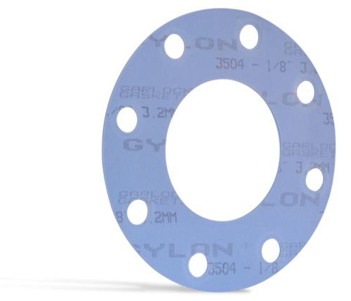
Gylon 3504
The GYLON® Style 3504 gasket is made of PTFE with aluminosilicate microspheres. It is designed for use in many acids, some caustics, hydrocarbons, refrigerants, and more.
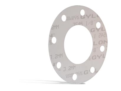
Gylon 3545
The Garlock 3545 style is a highly compressible microcellular PTFE with a rigid PTFE core for improved handlability. Garlock 3545, made with Gylon material, is designed to compress and conform to irregular or damaged surfaces, making it suitable for flanges that generate lower compressive stresses, such and glass-lined flanges and equipment.
INDUSTRY
Food & Beverage – Wine Production
CUSTOMER
An award-winning, family owned & operated winery in the heart of a major US wine-growing region.
BACKGROUND
The customer crushes, presses, ferments, bottles, and labels all of their wines at their winery, but having traditionally utilized EPDM gaskets, they faced ongoing issues with seal reliability. This was occurring during various stages of the winemaking process, but especially so during the sterilization procedures between each batch, with subsequent leaks creating issues in production reliability, housekeeping, and potential contamination.
CHALLENGES FACED
Business was growing rapidly so new equipment had been installed, but at the same time the number of maintenance windows was reducing. Therefore the customer was looking for a more reliable and sanitary product to improve efficiency and help to protect the sensitive product. As well as the need to remain absolutely compliant with industry standards, the customer also placed utmost importance on prevention of any adulteration of their award-winning wine. As well as working around limited windows of opportunity for production trials the critical and expert opinion of wine tasters was therefore essential to ensure full approval of any component change in the process.
- May 02, 2019
How this feature can improve performance and efficiency with gaskets
Gaskets have always been part of industrial production. However, gaskets have not always been forgiving, easy to use or simple to remove. What if the sealing products were designed to optimize the work put into them? What if the design had a level of intelligence built in? What if the design could make up for equipment damage? When used properly, enhanced surface profiles for gaskets can reduce leaks, spills and other releases that can damage the environment, put people at risk, result in fines and lead to costly downtime.
Using surface profiling to reduce area and increase stress is found in everyday life, from the soles of running shoes to the treads on vehicle tires. Reducing the contact area while maintaining compressive force results in increased stress. In the case of gaskets, traction or friction between a gasket and the flange faces is critical to holding internal pressure. If the downward force created by the fasteners in a flange is diluted or spread over a larger area, the overall stress is reduced.
Compressibility
Adding raised features to the surface of a gasket to reduce contact area and increase stress also tends to impact compressibility. Compressibility represents the ability of the gasket to conform to the surfaces it is being used to seal. Flange surfaces usually show signs of wear, pitting, scratches or other defects. It is cost-prohibitive to make two mating flange faces smooth and flat enough to seal without a gasket. The more compressible a gasket is, the better chance the user has of attaining an effective seal.
Image 1. (clockwise left to right) Traditional material sees heavier load around the gasket bolts and lighter load farther from the bolts. Image 2. Load distributed more evenly. Image 3. More stress toward the bolts. Image 4. Stress spread evenly around the gasket. (Images courtesy of Garlock) Pressure Resistance
Compressibility also impacts the amount of pressure exposure on the gasket. When a flange assembly is pressurized, the internal media pushes outward on the inner diameter of the gasket. The thinner a gasket becomes, the less outward force it sees from internal pressure. This is referred to as improved “blowout resistance.” Unfortunately, one common error made when a gasket blows out is to replace it with a thicker gasket. This puts more gasket surface in the pipe or vessel for the internal pressure to act on.
Sealability
To create an effective seal, there are two functions the gasket must accomplish.
First, it needs to conform to the flange face to prevent the media from passing between itself and the flange faces. This is where the compressibility is important.
- March 26, 2019
Fried Snack Foods and GYLON® Style 3504 Gasket
The GYLON Style 3504 gasket is made of PTFE with aluminosilicate microspheres. It is designed for use in moderate concentrations of acids, caustics, hydrocarbons, refrigerants, and more.
It provides a tight seal, improved performance over conventional PTFE, reduced product loss and emissions, reduced creep relaxtion, excellent bolt torque retention, it doesn't burn, will not support bacterial growth, plus many more benefits.
INDUSTRY
Food Processing – Fried Snack Foods
CUSTOMER
A major diversified food & beverage manufacturer, with facilities located in all regions across the globe.
BACKGROUND
The customer had persistent problems when sealing hot oil applications on its bulk snack food fryers across several production sites. Build-up of polymerised vegetable oil on the flanges caused unsightly mess, maintenance complications, financial implications, and posed a significant fire risk.
CHALLENGES FACED
As well as ensuring that the sealing material was compliant to FDA and EN1935 standards, the challenge was to ensure that the gaskets would perform well under the difficult conditions presented by the high oil temperatures. Additionally, because the production line was also subject to regular and aggressive cleaning cycles, the gasket material was required to be compatible with other aggressive chemicals across a broad pH range.
- February 26, 2019
Poultry Processing: KLOZURE® ISO-GARD®
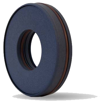
ISO-GARD bearing isolators offer exceptional bearing protection for pumps, motors, and bearing supported industrial equipment under the harshest conditions.
ISO-GARD products are constructed using a filled PTFE material which provides excellent chemical resistance.
INDUSTRY
Food - Poultry Processing
CUSTOMER
A diversified food processing company, with facilities located
throughout the US.BACKGROUND
The customer had persistent problems with sealing the bearings in their non-metallic feather picker housings. Using standard lip seals, and with a monthly maintenance program, they still encountered frequent failures. With 72 assemblies (each with two sealing locations) this had a detrimental effect on manufacturing efficiency, and placed a significant burden on the maintenance teams.
CHALLENGES FACED
Poultry feathers were getting under the lip seals and into the bearing housing, causing frequent and unexpected failures. Daily wash-downs also used a chemical cleaning solution that could also damage the bearings if not sealed correctly. Additionally, there was limited space available for any modification of sealing element.
Meat processing environments are highly regulated by the FDA, so any manufacturing changes must be carefully controlled. Therefore the customer required close support to ensure that any changes could be implemented with full confidence.
- February 12, 2019
Replacing Aging Water Infrastructure With NSF Compliant Materials
There are over 155,000 public water systems in the United States and more than 286 million Americans who rely on community water systems daily. Since most of the infrastructure was built between the early 1900's and 1960 using outdated technology/products and capabilities, nearly everything is approaching the natural end of it's lifespan.
Some estimates put the repairs and replacement of the infrastructure between $250B and $500B over the next 20-30 years. Several applications will need to be updated or fully replaced for the safety of consumers and quality of delivery, including:
- Joining and sealing materials
- Mechanical devices
- Pipes or related products
- January 29, 2019
Expansion Joint Control Units
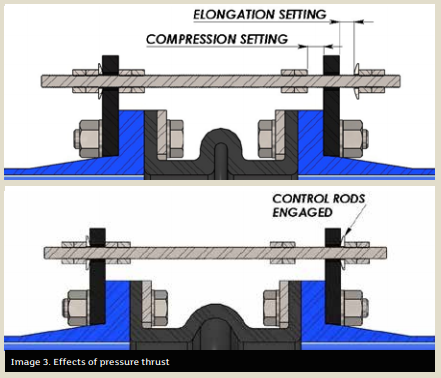
Elongation settings are a vital factor to assembly effectiveness.
It is no secret that one of the greatest demands for an expansion joint is the expectation to serve a long, leak-free life with little-to-no maintenance. Once installed, these flexible rubber connectors should require little attention. The preservation of this investment (and one’s sanity) can be maximized with an in-depth overview of how control units can prevent a new expansion joint from being overstressed.
The purpose of a control unit is to act as a safety device against excessive movement resulting from pressure thrust. A typical control unit assembly is comprised of threaded rods, steel gusset plates, nuts and washers (see Images 1 and 2).
The usage of control units with an expansion joint is always beneficial; pressure spikes during a system upset can cause uncontrolled surges through the expansion joint. This is a prime example of how valuable it is to have control units installed to protect these rubber assets from damage.
Methods to the Madness
A common misconception about control units is that they are designed to support the weight of pipe members or act as a substitute for adequate mounting. They are not. The sole purpose of a control unit is to allow the expansion joint to move freely within a specific range of movement while preventing the joint from being overstretched from pressure thrust forces.
The control units in no way impede the joint from performing its other duties beyond movement (vibration absorption, cycling or compensation for misalignment). The few extra steps needed to install the control units with the expansion joint could pay notable dividends in the long run.
Pressure thrust plays a huge role in how an expansion joint functions. While under pressure, the forces acting on the inside walls of the expansion joint actually cause the joint to swell and elongate. In the real world, an expansion joint is held comfortably between two pipe flanges, which in most cases are restrained by a pump lagged to the floor or mounted to a structural beam. Although it may not be apparent to the naked eye, once the expansion joint sees pressure, it produces a thrust force that acts axially on both pipe flanges.
Theoretically, what would be the result if the expansion joint was unrestrained on each end while pressurized?
Without fixed ends, the pressure thrust would force the joint to elongate without bounds.
Most useful in high pressure applications, the control rods will engage with the gusset plates once a pre-specified amount of growth for the expansion joint has been reached, restricting the joint from stretching any further. At this point, the control rods are absorbing any additional thrust acting on the pipe flange, thus limiting the amount of stress that is exerted onto adjoining equipment.
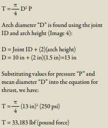
The design theory for sizing control unit hardware is based on the pressure thrust. Nominal inside diameter (ID) and arch geometry of the expansion joint are key drivers for calculating the thrust force that will be applied to the pipe at maximum line pressure. Per
industry standards set by the Fluid Sealing Association (FSA), both control rods and gusset plates are designed to withstand no more than 65 percent of the yield strength of the material.
Magnitude of the pressure thrust can be calculated by knowing the internal pressure and the effective area of the expansion joint. Effective area is found using the arch diameter of the expansion joint, which takes into account the size of the arch.
For example, we can calculate the resulting pressure thrust for a 10-inch ID expansion joint using an arch height of 1.5 inches that is rated for a maximum pressure of 250 pounds per square inch (psi).
The equation for pressure thrust “T” is:
These design limitations based around yield stress are the reasons why some control units made from lower yield strength stainless steel contain thicker components or more rods per set than the standard carbon steel control units.
Installation & Inspection
For a control unit assembly to be effective, rod positioning and elongation settings are critical during installation. Each control rod should be evenly spaced around the flange to best distribute the load. Elongation settings (see Image 5) are often overlooked, yet are a vital factor to ensure the control units fulfill their intended use.
Every expansion joint comes with movement ratings based on arch size, configuration and number. These movement design ratings of the expansion joint are critical pieces of information that are absolutely required during the installation of control units. The general rule of thumb is the gap between the gusset plate and the nut should be adjusted to match the joint’s elongation rating.
Having this information at hand during installation is great, but what about the existing control units currently in operation? Visual inspections of these components are a basic task that goes a long way toward extending the life of the joint.
Here are the top 4 anomalies to look for when performing a field inspection:
- January 14, 2019
Over-tightening, excessive speed and improper installation can cause a system to falter.
In many respects, troubleshooting and failure analysis of compression packing materials is similar to the investigation of a crime scene. A good investigator knows how to gather clues from many different sources and put them together to understand what has happened. A good troubleshooter uses the same information gathering method, familiarizing themselves with the sealing materials, the process equipment and the systems where they are used.
Start by Interviewing Witnesses
The troubleshooter should seek information from the people who work with the equipment on a regular basis. Seal installers, maintenance personnel, operators, process engineers and others can all shed light on potential causes of failure. Some key questions should be:
- How is failure defined? Some examples include excessive leakage, overheating, high rate of flush water consumption, excessive friction load and blowout.
- Is this application the source of chronic seal failures, or was this an unexpected event?
- Were there any changes to the seal material, the equipment or the overall process that preceded the failure?
- Were there any system upsets or cleaning cycles that preceded the failure?
- Can you describe the installation procedure?
Gather Information About the Victim
Knowing the limitations of the sealing product is a key step. The acronym “STAMPS” will help remember the key elements to ensure the right packing is selected for the application.
- S: Size. Is the correct packing cross-section being used? Are the rings cut or formed to the correct length?
- T: Temperature. Check the system temperature against the packing manufacturer’s established temperature ratings for the product.
- A: Application. Some packings are made specifically for rotary equipment while others are intended for valves or static seals. Check to make sure the packing is suitable for the equipment where it is being used.
- M: Media. This refers to the fluid being sealed. Check with the manufacturer or with compatibility charts to be sure the seal material is compatible with the media. If the media is slurry, abrasion-resistant materials may need to be specified. If the media is toxic, explosive or required to be contained within certain maximum allowable leakage requirements, then a packing must also be selected on the basis of its ability to seal at low leakage levels.
- P: Pressure. Check the system pressure against the packing manufacturer’s established pressure ratings for the product.
- S: Speed. Check the equipment speed against the packing manufacturer’s established surface speed ratings for the product. Surface speed is expressed in feet per minute or meters per second and not revolutions per minute.
Investigate the Crime Scene
When possible, observe the equipment while it is running. Can you see, hear, feel, smell or use a sensor to make observations? Smoke, vibration, grinding noises, the scent of burning fibers and system pressure fluctuations are only a few of the clues that can be noticed or measured while the equipment is up and running.
Examine the condition of the equipment. Most packings are robust seals that can handle less than perfect equipment condition, but there are limits to the amount of degradation they can withstand.
Valve stems and pump shafts or sleeves should be checked for scratches, corrosion pitting and general surface roughness. Rough surfaces can damage the sealing surface and result in excessive leakage and quick wear of the seal.
Image 1. Extrusion of the seal material Excessive clearances at the top or bottom of the stuffing box can lead to extrusion of the seal material and intrusion of large solid particle into the seal area (see image 1).
In severe cases, excessive clearance may result in a seal blowout.
Most packings are not meant to function as both a seal and a bearing. In rotating equipment, poor bearing condition may result in shaft runout that “wallows out” the inside diameter of the seal. Misalignment may result in shaft/stuffing box offset that causes one side of the packing set to be heavily compressed while the other side is compressed much more lightly. A similar side loading of a packing set can occur in large horizontally oriented valves where the packing is forced to bear the weight of the stem.
Check to make sure all the parts are in place. During the breakdown, repair and reassembly of equipment it is possible to misplace parts. Equipment might be put back into service without seat rings, bushings, lantern rings, O-rings and other parts that are essential to proper equipment operation.
Look at the seal and the equipment as a part of a big picture.
Consider how this piece of equipment is affected by other equipment and control devices in the system. For example, is there a downstream valve that creates pressure spikes in an upstream pump seal when the valve closes and the pump is still operating?