Monthly Archives: January 2019
- January 29, 2019
Expansion Joint Control Units
Elongation settings are a vital factor to assembly effectiveness.
It is no secret that one of the greatest demands for an expansion joint is the expectation to serve a long, leak-free life with little-to-no maintenance. Once installed, these flexible rubber connectors should require little attention. The preservation of this investment (and one’s sanity) can be maximized with an in-depth overview of how control units can prevent a new expansion joint from being overstressed.
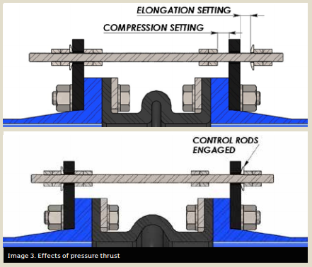
The purpose of a control unit is to act as a safety device against excessive movement resulting from pressure thrust. A typical control unit assembly is comprised of threaded rods, steel gusset plates, nuts and washers (see Images 1 and 2).
The usage of control units with an expansion joint is always beneficial; pressure spikes during a system upset can cause uncontrolled surges through the expansion joint. This is a prime example of how valuable it is to have control units installed to protect these rubber assets from damage.
Methods to the Madness
A common misconception about control units is that they are designed to support the weight of pipe members or act as a substitute for adequate mounting. They are not. The sole purpose of a control unit is to allow the expansion joint to move freely within a specific range of movement while preventing the joint from being overstretched from pressure thrust forces.
The control units in no way impede the joint from performing its other duties beyond movement (vibration absorption, cycling or compensation for misalignment). The few extra steps needed to install the control units with the expansion joint could pay notable dividends in the long run.
Pressure thrust plays a huge role in how an expansion joint functions. While under pressure, the forces acting on the inside walls of the expansion joint actually cause the joint to swell and elongate. In the real world, an expansion joint is held comfortably between two pipe flanges, which in most cases are restrained by a pump lagged to the floor or mounted to a structural beam. Although it may not be apparent to the naked eye, once the expansion joint sees pressure, it produces a thrust force that acts axially on both pipe flanges.
Theoretically, what would be the result if the expansion joint was unrestrained on each end while pressurized?
Without fixed ends, the pressure thrust would force the joint to elongate without bounds.
Most useful in high pressure applications, the control rods will engage with the gusset plates once a pre-specified amount of growth for the expansion joint has been reached, restricting the joint from stretching any further. At this point, the control rods are absorbing any additional thrust acting on the pipe flange, thus limiting the amount of stress that is exerted onto adjoining equipment.
The design theory for sizing control unit hardware is based on the pressure thrust. Nominal inside diameter (ID) and arch geometry of the expansion joint are key drivers for calculating the thrust force that will be applied to the pipe at maximum line pressure. Per
industry standards set by the Fluid Sealing Association (FSA), both control rods and gusset plates are designed to withstand no more than 65 percent of the yield strength of the material.
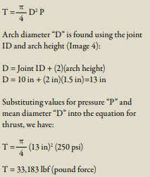
Magnitude of the pressure thrust can be calculated by knowing the internal pressure and the effective area of the expansion joint. Effective area is found using the arch diameter of the expansion joint, which takes into account the size of the arch.
For example, we can calculate the resulting pressure thrust for a 10-inch ID expansion joint using an arch height of 1.5 inches that is rated for a maximum pressure of 250 pounds per square inch (psi).
The equation for pressure thrust “T” is:
These design limitations based around yield stress are the reasons why some control units made from lower yield strength stainless steel contain thicker components or more rods per set than the standard carbon steel control units.
Installation & Inspection
For a control unit assembly to be effective, rod positioning and elongation settings are critical during installation. Each control rod should be evenly spaced around the flange to best distribute the load. Elongation settings (see Image 5) are often overlooked, yet are a vital factor to ensure the control units fulfill their intended use.
Every expansion joint comes with movement ratings based on arch size, configuration and number. These movement design ratings of the expansion joint are critical pieces of information that are absolutely required during the installation of control units. The general rule of thumb is the gap between the gusset plate and the nut should be adjusted to match the joint’s elongation rating.
Having this information at hand during installation is great, but what about the existing control units currently in operation? Visual inspections of these components are a basic task that goes a long way toward extending the life of the joint.
Here are the top 4 anomalies to look for when performing a field inspection:
- January 24, 2019
- January 17, 2019
Article re-posted with permission from Parker Hannifin Sealing & Shielding Team.
Original content can be found on Parker’s Blog.Contact GFS about battery sealing solutions >>
Sealing can often be a frustrating challenge when dealing with batteries and battery storage solutions. Determining what materials are compatible with certain chemistries or developing a profile that provides optimal sealing under available compression can be a time-consuming task for those outside the sealing industry. A trial and error approach can have a significant overall cost impact through multiple prototype iterations, prolonged testing, and ultimately, delaying product commercialization.
Specialized support
With Gallagher Fluid Seals and Parker Sealing's design and material engineers, we can provide support to your team in the critical, early stages of product development. With hundreds of engineered elastomeric materials to choose from, Parker and GFS can identify and recommend a compound that works with your specific electrolytes or other fluids. With the exceptionally long lifetime requirements of flow batteries, Parker's homogeneous rubber provides the elasticity needed to handle the many charge-discharge cycles the battery will see in its life.
- January 15, 2019
Installing Radial Shaft Seals
Radial shaft seals, also known as lip seals, are used to seal rotary elements, like a shaft or rotating bore. Hydraulic pump seals, axle seals, valve stem seals, or strut seals are the most common examples the average person would recognize.
Radial shaft seals are used in a variety of applications and perform two essential functions: the first is to avoid leakage through retaining the bearing or system lubricant; the secondary function is to avoid the contamination of the system by outside impacts (external particles or environmental issues).
- January 13, 2019
Acquisition will help expand Gallagher's industry-leading service and capabilities
Gallagher Fluid Seals, Inc., a global distributor and manufacturer of fluid sealing products located in the Greater Philadelphia area recently made an acquisition to further expand it's industry-leading service and capabilities.
On January 2, 2019, Gallagher Fluid Seals, Inc. acquired Quality Seals based out of
- January 10, 2019
Gaskets from NA 1122 Compressed Non-Asbestos Sheet Material
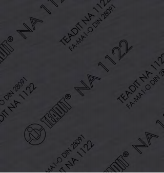
For nearly five decades, the fluid sealing industry attempted to pinpoint an ideal solution to replaced asbestos-based gaskets... until recently. TEADIT's NA 1122 is a Compressed Non-Asbestos sheet rubber specially formulated for severe-service applications.
NA 1122 sheets provide a new option that meet the needs of users while helping to avoid the hazards of using asbestos-based gaskets in the workplace.
TEADIT style NA 1122 was developed to exhibit superior thermal stability during extreme thermal cycling applications. It is specifically recommended for saturated and superheated steam services but has also proven itself to be very effective in sealing liquid petroleum derivates, ethanol, chemical products and other fluids.
- January 08, 2019
Article re-posted with permission from Parker Hannifin Sealing & Shielding Team.
Original content can be found on Parker’s Blog.
The Difference Between Thermal Conductivity and Thermal Impedance
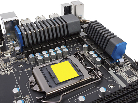
Thermal Interface Materials (TIMs) are useful for thermal management in electronic components, as they enhance heat transfer from a heat-generating component to a heat dissipater, or heat sink. One important aspect when selecting a TIM for your application is knowing the material’s ability to transfer heat, which is often given by way of thermal conductivity and/or thermal impedance.
Across the industry, manufacturers often publish thermal conductivity in units of Watts / meter-Kelvin as well as thermal impedance in units of °C – inches2 / Watt on their datasheets. So, what is the difference between these two, and how should you consider them when selecting a TIM?
Thermal conductivity is a material property and describes the ability of the given material to conduct heat. Therefore, when a material’s thermal conductivity is high, the material is a better thermal conductor. This property is independent of material size, shape or orientation in a homogeneous material, and because of this, thermal conductivity is an idealized value.
To understand thermal impedance, we must first understand thermal resistance and thermal contact resistance.
- January 04, 2019
Metal Hose Applications
Metal hose applications can be tricky. Hoses can fail or have a variety of other problems due to a few different factors: improper installations or outside factors from the surrounding piping system. In this video, Erik Kane, Hose Master's Product Specialist, discusses various do's and don'ts when installing metal hose. Follow these tips and more to help maximize the life of your hose and optimize your safety.


