Application for Open Credit terms is now available when shopping on our eCommerce platform! If interested, please download, fill out, and resubmit the application form in the "Open Terms Information" tab within "My Account". You will be notified when approval and credit limit is confirmed with our team.
This post is the third installment in a three-part series that describes the three main criteria for O-ring gland design: stretch, squeeze, and volume fill. These three related components must be balanced to create the ideal conditions for O-ring sealing.
Understanding the basics of volume fill
The final essential criterion for O-ring design is volume fill, also called gland fill. The compressed O-ring must have extra space within the groove without overfilling the groove. Volume fill is the O-ring volume divided by the gland volume.

For standard O-ring grooves in the face and radial applications, we recommend 60-90% gland fill. The O-ring must have room to expand laterally in the groove due to axial compression. The extra void space in the design allows the O-ring to swell slightly due to thermal expansion or fluid exposure without damaging the seal. Overfilling the groove can damage the O-ring or hardware and result in leakage. If the compression is appropriate and the volume fill is high, the simplest solution is to widen the groove.
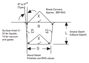
Elastomers are generally considered incompressible, meaning they have a Poisson ratio close to 0.5. In practical terms, this means that if the seal is compressed axially, it must deflect equally outward in the other two directions. The volume of the seal does not change by compressing or stretching it. For this reason, O-ring grooves are rectangular with a shallower dimension gland depth, “L” dimension in the figure above, providing the squeeze required and the longer groove width dimension labeled “G” provides the space to compensate for the compressed O-ring. Most volume-overfilled designs need a wider groove.
For standard O-ring grooves, two possible groove widths are shown in some design charts, one for liquids and the other for vacuum and gases. The extra width for liquids allows for some minimal volume swell and can better accommodate the tolerances. In vacuum applications, the narrower width allows for a faster pump down and reduces dead volume in which gas can be trapped.
High-volume fill designs
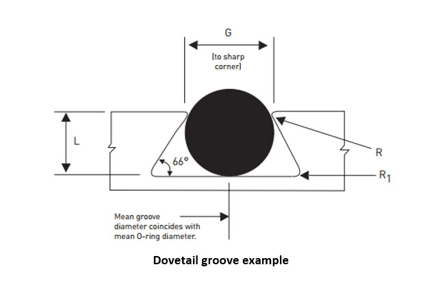
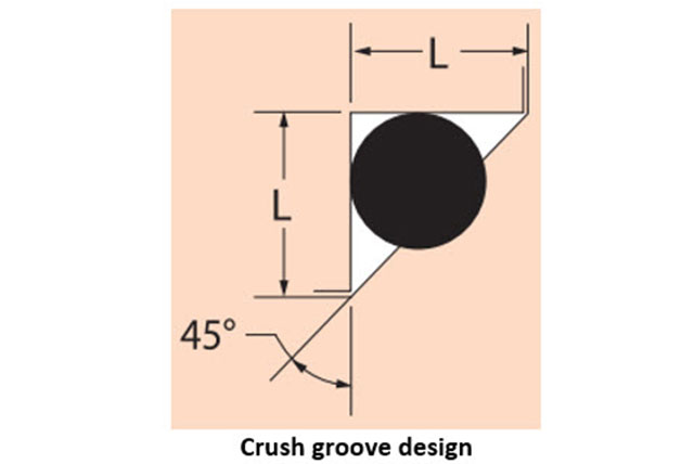
Dovetail grooves and Crush grooves are non-rectangular and are designed intentionally to 95% maximum gland fill. This can make them challenging designs when it comes to overfill. The designer should be especially conscious of the effects of thermal expansion and chemical compatibility for these high gland fill designs.
Failure mode: gland overfill
Gland overfills are a common failure mode for O-rings that can result in a combination of symptoms. If the application has a lot of force available to compress an over-filled seal, two things can happen:
The seal gets damaged as it is pressed out of the groove. This can appear like extrusion failures, but for gland overfill, the rubber often squeezes out of the groove on both sides, as shown in the below illustration. O-rings tend to extrude only on one side, opposite the pressure for extrusion failures.
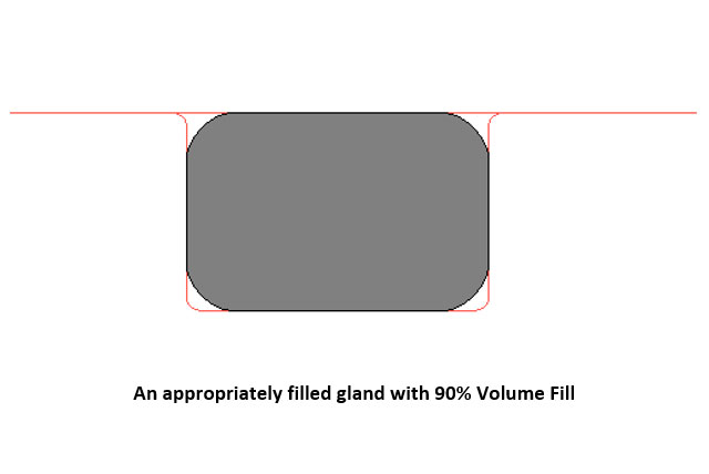
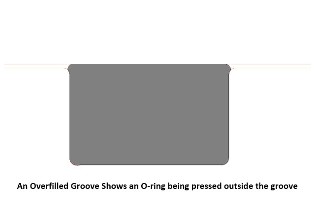
The second situation that can happen is that the mating hardware gets damaged. Customers tend to expect that a soft elastomer can’t damage their steel, aluminum or plastic hardware. Still, this frequently happens when an application has been designed for the O-ring gland to be overfilled.
If the application doesn’t have much force available for face seals, there’s a risk of not obtaining enough compression to seal adequately. For example, if the nominal O-ring requires 10 pounds to compress 15% and the hardware can only apply 10 lbs., then at 100% volume fill, the 10 pounds might only result in 5% compression, which is usually not enough for robust sealing.
Causes for unexpected gland overfill
Sometimes an O-ring tolerance stack up from the O-Ring Selector or Mobile InPhorm will show adequate gland fill, but the seal shows damage in an application. This can result from thermal expansion or swelling due to chemical incompatibility.
Seal materials have a higher thermal expansion coefficient than most hardware materials, so they are more greatly impacted by heat. For most applications, there must be a sufficient squeeze to prevent leakage at room temperature and a broader groove to compensate for thermal expansion. If the operation is only to be at a high temperature, gland volume may need to be increased to compensate for the thermal expansion of the O-ring. The Parker O-Ring Handbook has Table 2-4, which lists the approximate rate of linear thermal expansion for typical elastomers and other materials and may be utilized to calculate compensated gland dimensions.
Chemical incompatibility can also result in volume overfill. For static O-ring applications, some volume swell can be tolerated, but less swell is acceptable for dynamic applications as it may lead to friction and wear difficulties. Material compatibility charts within the Section 7 of the O-Ring Handbook provide insight into the expected swelling behavior of elastomer families. Chemical compatibility should be considered primarily for long-term immersion, “splash” or short-term exposure to fluids should be less of a concern.
Article re-posted with permission from Parker Hannifin Sealing & Shielding Team.
Original content can be found on Parker’s Blog.
Gallagher Fluid Seals is a Seal Technology Center for Parker. The STC is reserved for Parker’s premier level distributor network, for those distributors who drive value-added services to the mutual customer base.


