Eclipse Engineering
- January 17, 2020
Eclipse Engineering has in-house capabilities to manufacture seals up to 55 inches in diameter, and over 100 inches through production partners.
While seals with huge diameters certainly grant their own significant levels of intricacy, here we’ll look at the other end of the spectrum: the micro-sized seals.
We won’t just look at a simple seal ring, but an inherently more complicated and geometrically detailed spring energized seal. As we’ll see, very small diameters make multiple manufacturing aspects more involved and challenging.
The Client’s Issue
A sealing solution in a customer's epoxy dispensing equipment. They needed an effective seal for the reciprocating rod responsible for the flow-control and metering of the epoxy while being dispensed.
Operating Conditions:
- Reciprocating Rod Seal
- Epoxy Dispensing Head
- Rod Diameter: 1.2mm [0.047”]
- Stroke Length: 6mm [0.236”]
- Cycle Rate: 15 per min
- Media: Epoxy
- Operating Pressure: 1,500 PSI
- Temperature: 70° to 150°F
In general terms, most viscous media sealing solutions have three things in common:
- A variant of UHMW for the seal jacket,
- heavy spring loading, and
- multiple point contacts with increased interference.
In most cases, multiple nested V-Springs are incorporated to provide optimal load and energize the compound contact points on the seal. With this formula, we’ve had great success sealing media like epoxy, urethane, silicones and acrylics.
The heavy loading is necessary to effectively wipe the reciprocating rod. This is balanced with the correct material and design geometry to provide long wear life of the seal, which has the potential to be compromised under such loading.
The challenge in this case was to incorporate these same proven principles in a micro-sized seal.
The Eclipse Solution
- December 11, 2019
Back in the mid 70’s, an engineer named Roy Edlund of Busak & Luyken designed a high-pressure seal that had an uncommon effect of rocking in the groove. This action occurred when pressure was created on the retract side of a cylinder as the rod was being retracted into the cylinder.
The material used for the seal was generally a bronze-filled Teflon, which could resist extrusion and have a long seal life. Because the seal ring was made from a grade of filled Teflon, a small amount of oil would leak under the lip as the cylinder was being extended.
One of the most unique features of this style seal was that as the rod was being retracted back into the cylinder, the buffer ring would rock or rotate slightly to the low pressure side thereby forcing leaked oil back into the retract side of the cylinder under the buffer ring.
This seal is commonly called a Buffer Ring (for reasons we’ll explore in this blog), but this seal helped usher Teflon into most high-pressure hydraulic systems today.
Pre-Buffer Ring Sealing Problems
Manufactures of high-pressure hydraulic systems in equipment, such as back hoes or hydraulic cranes found that their products were having seal failures prior to reaching warranty. This resulted in downtime and large warranty expense to repair these cylinders in the field.
In normal operations, the standard U-Cup made from a variety of Urethanes did an excellent job of creating a “near” zero leak sealing system. The problems would occur as the “bulk” oil temperature rose due to usage, pressure spikes in the system would cause premature failure of the Urethane U-Cup.
It was the pressure spikes that usually wreaked havoc with the U-cup seal design, causing the urethane to break down and eventually crack, creating a leak, and resulting in equipment shut-downs.
The Buffer Ring Solution
The Buffer Ring turned out to be the answer. By adding another sealing element in front of the Urethane U-cup, the life of the U-cup was greatly extended, overall friction in the system was reduced, and the bulk temperature in the hydraulic system was lowered.
All these advantages came by adding a sealing element. The true savings showed up in dramatically improving equipment up time. This also reduced warranty costs of equipment to the OEM.
How Does the Buffer Ring Work?
The answer to this question was initially difficult for many manufacturers to understand. Normally, putting one seal in front of another should cause a pressure trap, sending pressure loads much higher than relief valve settings, which locks up the cylinder.
The secret was in the way the Buffer Ring performed its job.
The seal leaking is very important to its design. If oil didn’t reach the U-Cup, the U-cup would generate heat and begin to wear out prematurely. So, since the Buffer Ring allowed a small amount of fluid to seep under the lip, this fluid lubricated the U-cup and kept its friction to a minimum.
Being elastomeric in nature, the U-cup did an excellent job of wiping the rod nearly completely dry.
But what about the pressure trap?
The Buffer Ring and its unique quality allowed fluid back into the system. Testing verified that this would happen anywhere from zero to about 100 PSI.
The U-cup spent most of its life in a well-lubricated, low-pressure / low-temperature environment compared to the original design.
The Buffer Ring also made suppliers of U-Cups extremely happy, as their failed seal had been given new life compared to the holes blown through the back of their urethane product.
- November 12, 2019
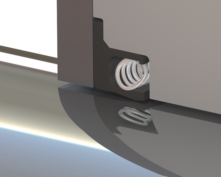
Springs are an integral part of all sealing systems. A simple air cylinder has O-rings to seal in the air, and the O-ring exhibits spring-like qualities to ensure a good seal over a broad temperature range.
But what are the different types of springs and materials in sealing systems? And how do you choose the best for your application?
Metal Springs
Metal springs, such as the Cantilever and Canted Coil spring, are used to energize polymers such as Teflon and ultra high molecular weight polyethylene (UHMW) to allow sealing in a wide range of temperatures. Selecting the correct spring material is critical to the life of the seal.
Metal energized
- October 11, 2019
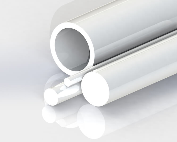
Better known as Teflon in the industry, Polytetrafluoroethylene is widely used in practically every industry on and off the planet (and even beneath its surface!)
Medical Uses
This material’s primary claim to fame is its resistance to most chemicals. It inherently has an extremely low coefficient of friction, it’s easily machined from rods, tubes, or compression-molded shapes.
It’s one of the few polymers that are approved for medical implants due to its inertness to bodily fluids — the immune system principally ignores its presence in the body.
Moving away from the body, you’ll find PTFE or Teflon products in medical
- September 24, 2019
A ball valve is a simple and robust valve used in applications and industries across the spectrum. It consists of a ball with a hole through the center that can be rotated 90°.
The hole is either aligned with flow and open, or perpendicular to flow and closed. The straightforward, quarter-turn action is fast and simple to operate, and the position of the handle provides a clear indicator of whether the valve is open or closed.
Most ball valves are typically used as a shut-off valve. Many households likely use ball valves at some point in the water supply plumbing.
Not relegated to common plumbing, many industries use ball valves for critical control applications including aerospace and cryogenics. Their reliable operation and high-pressure handling ability make them an attractive solution for many specialty operations.
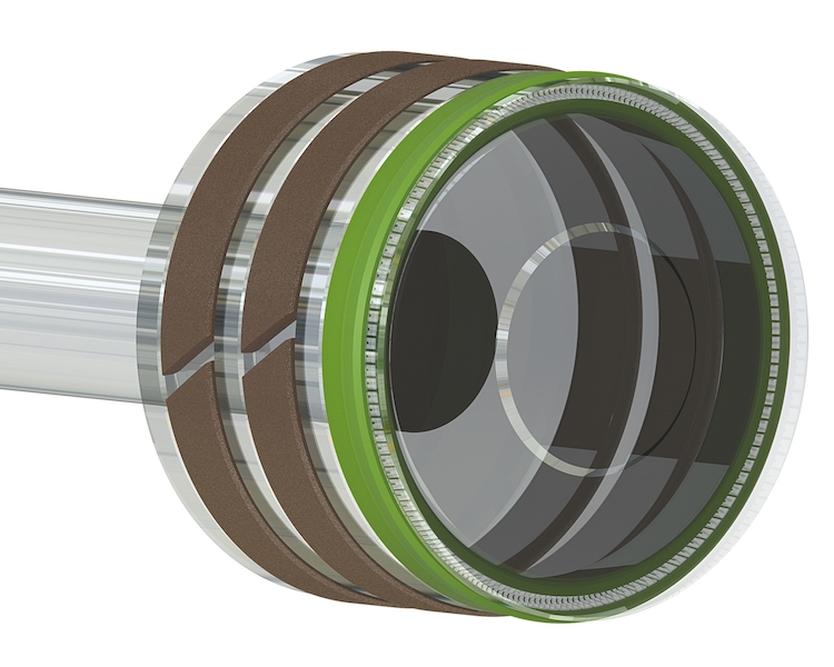
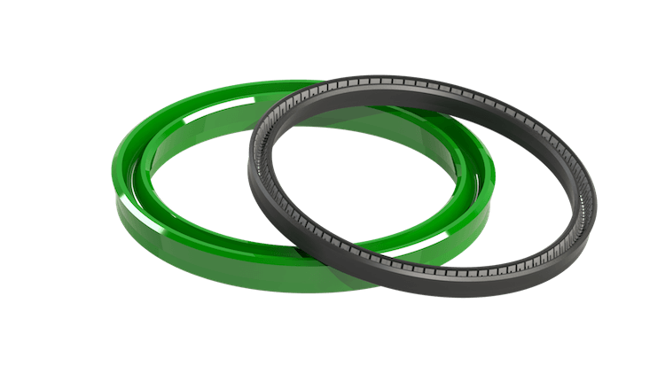
Seals Inside a Ball Valve
The seals inside the ball valve play an important role in their performance and reliability. There are two main seals in a common ball valve, which are referred to as seats.
The seats are typically machined or molded to match the diameter of the ball and are mechanically compressed against the ball face. Seat material varies by application needs, but virgin PTFE is frequently used for this application.
The Client’s Issue
The customer wanted a very specialized ball seat: utilizing a spring energizer in the seat. While easy to suggest, this would create a significant challenge in how the seal is manufactured.
The customer was looking for a sealing solution for a ball valve in their industrial gas processing plant. The ball valve would serve as a critical shut-off point in the system. The valve would be actuated by an electric motor, and could therefore be operated remotely.
The customer was looking for an improvement in the overall wear life of the ball seats, while still providing consistent and predictable actuation torque. Being motor activated, the torque required to move the ball open or closed was limited—so the friction generated by the ball seats would need to be carefully controlled.
Operating Conditions:
- Ball Valve Seat
- Ball Diameter: Ø2.500”
- Media: Petroleum Processing Gases
- Pressure: 100 PSI
- Temperature: -40° to 175°F
The Challenge
- August 29, 2019
Polymer wear rings were developed to offer an alternative to dissimilar metal wear rings.
One of the advantages to using a polymer material such as nylon or filled-Teflon instead of a metallic bearing . Whereas when you use bronze or metallic bushings, these materials are prone to point loading on the edges of the bearing.
This property of polymer bearings combined with solid lubricants can yield a product that is much less likely to damage moving components.
5 Advantages to Polymer Wear Rings
- Polymer style bearings can be held to very close tolerances in the radial dimension to provide support without excessively opening the extrusion (E) gap by a large amount. Polymer bearings such as filled Teflon can support a compressive load up to 1000 PSI. Nylons up to 36,000 PSI and polyester fiber with resin, up to 50,000 PSI.
- Hydraulic cylinders that are found in excavators often use higher compression materials because they experience extreme
- July 04, 2019
When it comes to designing and developing seals, the aerospace and industrial industries need a basis to allow production anywhere in the world.
One of the first PTFE (Teflon) standards, AMS3678, describes Teflon and the addition of fillers. This was used in conjunction with Mil-R-8791, which is one of the Mil specs describing a backup ring device.
The origin of all these specs dates back to the creation of the O-ring.
The Origin of the O-Ring Patent
In 1939, Niels A. Christensen was granted a U.S. Patent for “new and useful improvements in packings and the like for power cylinders.” These referred to improved packing rings made of “solid rubber or rubber composition very dense and yet possessive of great liveliness and compressibility.” These products were suitable for use as packings for fluid medium pistons (liquid or air). The improved packing ring is the modern O-ring.
There was a progression of standards for the O-rings created by individual countries, such as AS568, BS 1806, DIN 3771, JIS B2401, NF T47-501, and SMS 1586. Eventually, AS568 became more accepted in the industry.
The backup ring was originally created to help improve the O-ring’s ability to resist extrusion. Teflon was widely used as one of the materials for backup ring devices. Standards were created to unify the production of this Teflon device.
The Progression of Mil Specs
The progression of standard changes has led to AMS3678/1 for Virgin PTFE through AMS3678/16. These standards describe a group of Virgin- and filled-PTFE materials accepted by the industry for manufacturing seals and back-up ring devices.
Mil-R-8791 was canceled in February 1982. This spec was superseded with AS8791, which eventually evolved into AMS3678.
AMS3678 is a tool used by customers and Teflon suppliers to create uniformity in the manufacturing and processing of seal and bearing materials. The standard is inclusive of most of the compounds upon which the industry was built.
When customers approach with an old “mil spec”, they are pushed to the new AMS spec which is currently active. Eclipse manufactures to the spec so their customers will have the confidence that they manufacture to a known standard.
When crossing custom materials from well-known sources, customers are driven to an accepted spec that is equivalent to the original source of the material. This helps customers sell their products with internationally-known materials rather than custom, home-grown compounds that are often intended to single source those materials.
There are several qualifications of the spec that suppliers must observe. This includes dimensional stability tests. This test ensures the material has been properly annealed, and that the seal or backup ring will fit and function as it was originally intended.
Eclipse is uniquely qualified to supply parts to the latest AMS3678 specification. They understand the scope of the specification which allows us to ship parts with fully traceable certification.
AMS3678 helps validate a material to a customer to ensure they get the same material processed the same way with each order. Beyond this, there are other ways to determine what makes a part process-capable.
- May 30, 2019
Seal designers often feel caught in the constant struggle to balance the demands of a sealing application with physical and material constraints.
At Eclipse, it’s an engineer’s job to understand and weigh these limitations with the goals of the application. For example, when a customer needs an extremely low friction seal that also has very high sealability, there’s always a compromise that needs to happen.
A magical seal material that has the pliability and excellent seal characteristics of rubber, and the low-friction, high-wear resistance and temperature range of PTFE simply doesn’t
- May 07, 2019
Dynamic Sealing Applications
This article will discuss how we understand and control friction in dynamic sealing applications.
It’s easy to stop a leak in a system by just welding it shut. But when you create a dynamic application, you generally have a limited amount of power to move the device you’re sealing.
Friction is a force that must be overcome in all moving pieces. Controlling friction allows us to make efficient equipment that can have a long wear life and move with a limited amount of force.
There are many factors that drive friction up or down in a dynamic application. Although this blog will focus on shaft seals, the same considerations apply to piston or face seals.
Below we’ll cover the following factors and how they affect the friction calculation in our seals:
- Shaft material, hardness, and finish.
- If the system will operate when lubricated or dry.
- The system pressure or vacuum.
- System operating temperature
- Seal material and the types of fillers.
Seal Substrate
As a seal supplier, we usually like shaft materials to be hardened steel with surface finishes that are highly effective. Hardness above 50 Rc usually gives long wear life.
Having a good finish of 8 Ra. will insure long seal life and carry lubrication. However, depending on the application, there are times when a super finish of 2 or 3 Ra is justified.
Depending on shaft loading, there are many choices of surface finish that can reduce friction and improve the life of the seal. Understanding the bearing load under the seal helps to understand what finish is required to withstand the operating conditions.
There are some finishes that are detrimental to seal life. An example is a heavy chrome surface that looks sturdy, but usually can’t be ground smooth and is left with large peaks or valleys. Thin, dense chrome is often the opposite, giving good seal life if applied correctly. The engineers at Eclipse Engineering are prepared to make recommendations on hardness and finish.
- February 28, 2019
Being commodity items, U-Cups are readily available in a number of materials and can be found on-the-shelf from multiple distributors and manufacturers in many standard sizes.
Named for the shape of their cross-section, a U-Cup’s design will be pressure energized increasing sealing effectiveness when compared to a standard O-Ring.
This means as pressure increases, the sealing lips are continually forced into the mating hardware surface, ensuring good contact at all times.
The simple and easily moldable design is an effective sealing solution to many systems in both hydraulic and pneumatic applications. Modifications in lip thickness and inclusion of an O-Ring Energizer can tailor sealing loads and wear life to specific situations.
A key advantage to an elastomeric U-Cup is the relatively small and simple hardware space needed. Because of their flexible compounds, most U-Cups can be installed in a solid gland configuration.
A basic ID or OD groove is all you need for proper seal retention. Plus, no special tools or considerations need to be taken for correct installation.
U-Cups are available in many of the same compounds as standard O-Rings such as Nitrile, Fluorocarbon, and EPDM, but polyurethanes may be the most common material.
Urethane provides a good combination of elasticity/pliability and toughness. Therefore, it exhibits good sealing characteristics as well as, durability and wear resistance.
These desirable qualities make U-Cups an optimal solution for many sealing systems across multiple industries and they can be found in countless standard products. But Eclipse is approached many times a year with customers pushing the limits of standard U-Cups and in need of better solutions.
The Client's Issue
Eclipse was approached by a leading pneumatic cylinder manufacturing seeking a sealing solution for a unique application.
While U-Cups typically provide optimal sealing performance in pneumatic cylinders, this application presented a difficult challenge.
The air cylinder was to be used as an actuator for a latch on a large industrial oven. While pressures, speeds, and cycle times were nothing out of the ordinary, the temperature at which it had to operate at was — a continuous 500°F.