
Below is the third and final section of the white paper, which will discuss the importance of proper seal and groove design.
Proper Seal & Groove Design
As an example, an application requires an AS-568 size 110 o-ring, which has a cross section of 0.103” ±0.003”. If the tolerance on the groove depth for this seal is ±0.003”, the actual o-ring compression could cover a wide range. Consider a flange face seal design with a minimum required o-ring compression of 16%, at room temperature. The nominal groove depth, to guarantee a minimum compression of 16%, would be 0.081”. The o-ring compression, when installed at room temperature could actually be anywhere from 16% to 26.6%. However, at the application temperature of 200°C, the relative seal compression could be as high as 30.3%, for the perfluoroelastomer ring. At compressions above 30%, there is an increased chance of the o-ring splitting due to high internal stresses.
The following chart compares the performance of an FKM and FFKM seal under the conditions described above. The effect of chemical swell is not considered in this example.
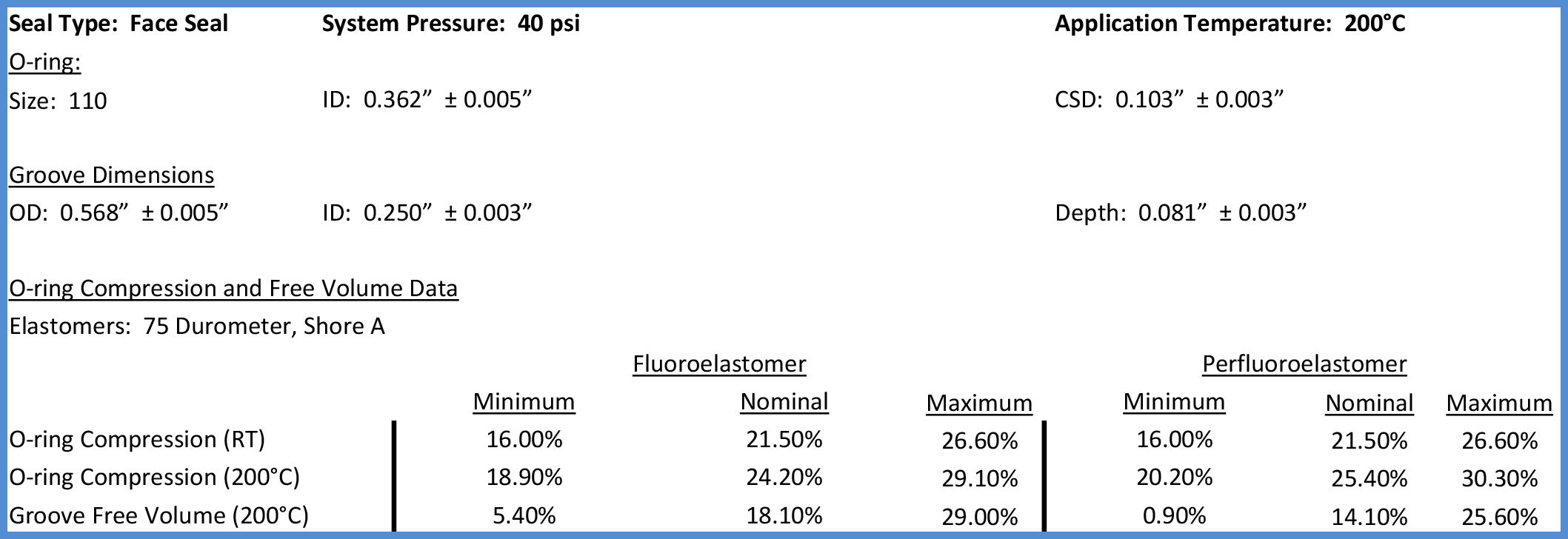
There are a couple factors to be noted from this data. First, at the application temperature of 200°C, the maximum compression on the FKM o-ring is lower than the FFKM o-ring due to the difference in CTE. This considers that both product formulations yield typical 75 durometer, Shore A, o-rings. O-ring formulations that are different durometers, usually due to the level of filler content, will have different CTE values. Second, note the difference in free volume in the groove, again due to the CTE. The implication is that perfluoroelastomers are not drop in replacements for fluoroelastomers, especially if the reason for change is due to high temperature. If the elastomer seal overfills the groove, the result will be extrusion and subsequent seal failure. To avoid unnecessary equipment downtime it is of prime importance to understand the application requirements when designing an elastomer sealing assembly.


