Fluid Power Applications - Part 1
We've previously spoken about Fluid Power Sealing Theory and the multitude of options when it comes to selecting the most suitable sealing product for your application. This article will be the first of a three-part series, focusing on common fluid power products, along with a description of the sealing systems that are typically used in those products. You can also download the entire Fluid Power Application White Paper by clicking on the image below.

Single Acting Hydraulic Ram Concept
Hydraulic rams are single-acting power cylinders that do not utilize a conventional piston. Instead, fluid pressure is applied to the end of the rod (ram) to create force for extension and either gravity or an external force is applied for retraction. The principal appeal of this design is its low manufacturing cost for large sized rams. Lower manufacturing costs are attributed to the fact that the cylinder bore does not require a close tolerance or a smooth surface finish. Only the ram itself needs to be ground and polished. Clearances are only important between the ram O.D. and gland I.D.
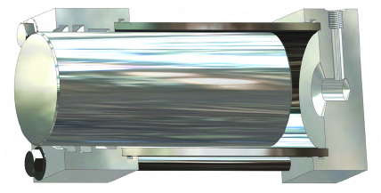
Rams that are retracted by gravity alone, customarily use low-friction lip-type seals, such as u-cups or squeeze seals made from PTFE. Low pressure sealing problems, characteristic of lip-type seals, are seldom significant as the throttled exhaust creates back pressure to energize the seal. Hydraulic rams installed in an upward vertical orientation collect contamination around the rod seal housing.
To prevent contamination from entering the cylinder, snap-in wipers are recommended. Wear rings or bearings are frequently required to prevent contact between polished rams and gland housings. Never rely on seals or wipers to provide lateral support.
If the ram is downward-acting, a spring or external retraction cylinder is used to return the ram into the cylinder. Normally, retraction cylinders are single acting and apply no force to the load. They can, however, be double-acting and add their force to that of the ram. In many applications, the ram is powered hydraulically, while the retraction cylinders are fast acting pneumatic units.
Externally retracted rams have more latitude in seal selection since the return force can overcome the extra friction of squeeze-type seals. Downward acting rams typically have low pressure return strokes which may produce leakage if lip type seals are used. Pressures are usually low during the down stroke until the ram contacts the load.
Single Acting Pneumatic Cylinder
Single-acting cylinders, as in the case of hydraulic rams, rely on mechanical means to retract or extend the rod. The cylinder shown is a typical pneumatic design, using an internal spring to extend the rod and air pressure to retract. The spring and pressure port arrangement could be reversed to provide power extension and spring retraction. The piston seal is typically a rubber u-cup profile. To maintain pre-lubricated surfaces a rounded lip profile can be selected for sealing the piston, and the rod if required.
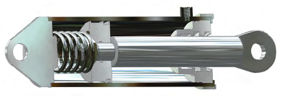
To reduce cost, O-rings are sometimes considered for pneumatic applications. This can be problematic since O-rings will wipe away pre-lubrication and are prone to instability, spiral failure, high friction, and rapid wear. Selecting u-cup seals will eliminate these problems.
Snap-in wipers are typically used to prevent contamination from entering the cylinder. These can be either polyurethane or rubber depending on the environment. Bearings for these types of cylinders typically do not see heavy side loads. Filled PTFE wear rings or strips are an excellent choice to ensure low friction performance.
Double Acting Power Cylinder
In double acting cylinders fluid pressure is applied to either side of a piston to extend or retract the rod. This is typical of many fluid power cylinders used for hydraulic or pneumatic service at low to high pressures. As shown in Figure 3, seals are required for both the piston and rod glands. Clevis mountings at each end of the cylinder permit alignment with external linkages without bending the rod.
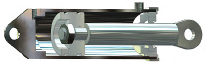
There are many options available to seal double acting cylinders. Dual grooves shown in the piston are designed for a pair of uni-directional (single-acting) seals installed “back-to-back” such that their sealing lips face away from one another. This orientation allows any fluid that passes by the pressurized seal to easily leak past the unpressurized seal, thus preventing pressure trapping. Never install seals back to- back with their sealing lips facing one another. This orientation will leak fluid into the space between the seals and pressure trapping will occur. Do not install dual seals in the same groove. The unpressurized seal will not support the pressurized seal resulting in instability and extrusion damage.
The other option to seal the piston is to install a bi-directional seal into a single groove. A single bidirectional seal eliminates installation confusion and the possibility of pressure trapping. Selecting a bidirectional seal allows more room on the piston for a wear ring to protect against piston and bore contact. Typically, the wear ring is located on the end cap side of the piston to maximize distance between piston and rod bearing surfaces.
In low to medium-pressure cylinders anti-extrusion back-up rings are not normally required. High pressure may cause the cylinder to expand (breath) allowing the seals to extrude into the clearance gap between the piston and the bore. This may also occur at lower pressures in thin-wall, lightweight cylinders. To protect the seals, back up rings are recommended.
Rod seals may be either uni- or bi-directional, squeeze or lip-type, depending on the application. As pressure requirements increase, and/or stroke and cycle rates increase, the use of multiple profile sealing systems (buffer and rod seal) are recommended. Rod wipers should be selected to match the application. Moving from snap-in wiper profiles to press fit profiles increases contamination protection. The wiper gland makes it easy to remove and inspect or replace the rod seal. To protect the seals from side loading, the internal side of the rod seal housing can be extended to make room for rod wear rings. Normally such side load forces should be avoided due to their tendency to bend the rod, accelerate wear, and restrict freedom of motion.
Telescoping Power Cylinder
Telescoping cylinders are usually single-acting cylinders which require an external force, such as gravity or a connected load, for retraction. Through a series of staged extensions this cylinder type provides a long stroke from a much shorter retracted length. They are used extensively to raise hinged beams or booms and dump
truck bodies.
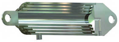
Figure 4 shows collars made of bearing metals which would be compatible with the tubing metal. Grooves to hold wear rings can also be designed into the collars. In rod type telescoping cylinders where O.D. sealing is employed, it is simpler to maintain lubrication of these bearing surfaces since both seal and wiper ring would be located in the outboard collar, and the bearings could be immersed permanently in the fluid.
The next section of this three part series will discuss Cushioned Double Acting Cylinders, Dual Fluid Power Cylinders, Ram Type Pressure Intensifiers, and Double Acting Annulus-Type Pressure Intensifiers. Please contact us with any questions regarding Fluid Power Applications and how we can help seal your fluid power systems.


