Fluid Power Applications: Part 2
We've previously spoken about Fluid Power Sealing Theory and the multitude of options when it comes to selecting the most suitable sealing product for your application. We also published the first article in this three-part series, which covered a handful of Fluid Power Applications. This article is the second of a three-part series, focusing on common fluid power products, along with a description of the sealing systems that are typically used in those products. You can also download the entire Fluid Power Application White Paper by clicking on the image below.

Cushioned Double Acting Cylinder
Cushioned cylinders provide a means of decelerating the piston during the last part of its stroke. This prevents hard impacts which could be destructive to the cylinder and the connected load. While this feature may be provided in many ways, a common design uses a deceleration cavity through which the fluid exhausts during retraction and extension. To reduce fluid flow a rod extension (end cap side of piston) and enlarged rod (spud) are added to obstruct the exhaust cavity at each end of the stroke. In the design shown, the remaining exhaust is forced through a metering valve which can be adjusted for the desired deceleration. When flow is reversed, check valves in each end of the cylinder by-pass the obstructed flow, permitting rapid acceleration. This is further improved when the rod extension or spud clears the port.
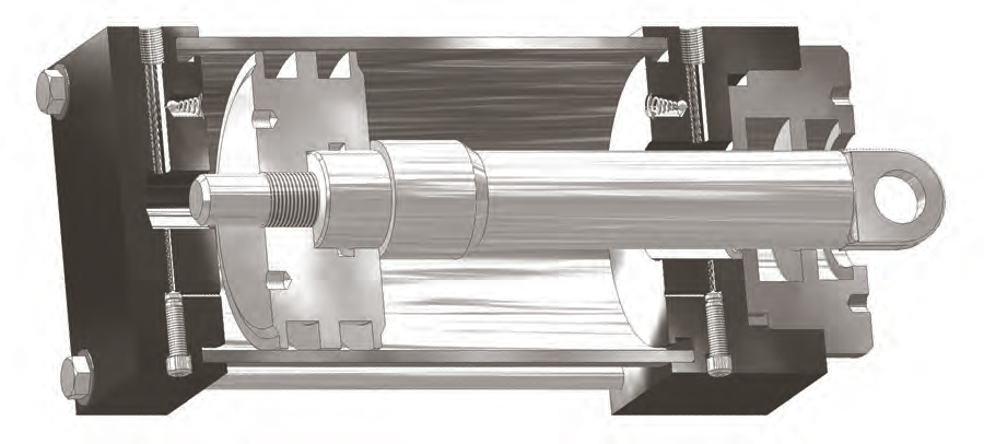
As for other areas of the cylinder that require dynamic seals, they would be selected based on the application parameters. Seals, wipers and wear rings for the piston and rod follow the guidelines described for dual acting cylinders.
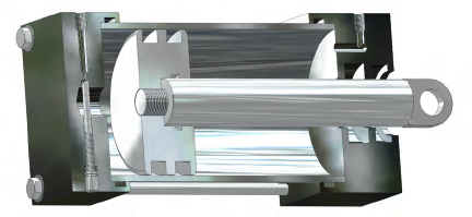
Dual Fluid Power Cylinder
In some applications it is desirable to utilize one fluid (such as compressed air) to drive a cylinder, along with a second fluid (hydraulic fluid) to regulate the cylinder speed. Being virtually incompressible, hydraulic fluid makes a better regulating fluid than compressible gas. The basic design in Figure 7 shows a cylinder in which the rod end is pneumatically driven, and the blind end is hydraulically restrained and regulated. A metering or throttling valve may be adjusted to control the retraction speed. If the hydraulic fluid is transferred into a low-volume accumulator with a captive volume of pressurizing gas, travel will slow down as the reservoir fills and back-pressure builds. If the accumulator is large in relation to the cylinder volume, stroke speed can be held nearly constant for the full travel.
While some lubrication assistance is provided by the hydraulic fluid, it is not prudent to rely on it for the total lubrication of the pneumatic end of the cylinder. If long seal life is required, internally lubricated compounds are recommended.
To create a gas spring or dampening effect, it is possible to reverse the ends of the cylinder to apply pneumatic pressure to the blind end, achieving a larger net area and consequently higher force while making it a “push” cylinder. With hydraulic fluid at the rod end, the rod seals are constantly lubricated. Also, since the hydraulic fluid is continuously under pressure, it is possible to use lip-type seals with negligible low-pressure sealing problems.
Ram Type Pressure Intensifier
Pressure intensifiers utilize the area ratio between the power piston and the ram as a means to multiply output fluid pressure. Inversely, the volume of the output fluid is reduced by the same ratio. Numerous pressure intensifier designs have been mass produced. The great majority are of the ram type, similar to that in Figure 8. They may be powered by the same fluid as that being boosted to a higher pressure, or by a different fluid. Typical examples include combinations of air, water, steam and oil.
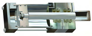
To ensure extrusion resistance, care should be taken when selecting seals for the intensified fluid. It may be necessary to include an anti-extrusion device to protect the high pressure seal from extrusion.
Double Acting Annulus-Type Pressure Intensifier
A popular design for pressure intensifiers is the annulus-type, which utilizes an enlarged rod diameter to provide differing piston effective areas on opposite piston faces. The net effective area on the rod side equals the full piston area minus the rod area. The ratio of the full piston area to the net area of the rod side establishes the intensification ratio.
A significant difference exists between this design and the ram-type intensifiers previously discussed. The pressure direction across the piston seals is reversed. Note that the lower fluid pressure acts on the larger piston face and the intensified pressure is on the inboard annular face. This means that the seals, if uni-directional, must be oriented with their sealing lips facing inboard. It also means that if the seals are installed in piston grooves, the direction of seal drag will encourage extrusion by adding to the intensified pressure. By installing the piston seals in wall grooves, as shown, friction is subtracted from the pressure forces, thereby minimizing the extrusion tendency. By the same logic, if the seals for the rod are installed in wall grooves, the direction of seal drag along with pressure act together to increase the extrusion tendency.
If the intensification chamber (the annular volume) is recharged by fluid under pressure, the double acting version shown will produce higher intensified pressure. This is achieved by adding the force developed in the annulus.
The intensified output pressure would be:
• Output Pressure = Aa +Ap x Pp / Aa
• If the annulus is recharged by a fluid at a different pressure than that of the power fluid (Pp), the intensified output
pressure would be:
• Output Pressure = (Aa Pp + Ap Pp) / Aa
In these equations:
- Aa = Annulus Area
- Ap = Piston Area
- Pa = Recharging Pressure
- Pp = Power Fluid Supply Pressure
As with the ram-type intensifiers, it is often preferred to mount this type vertically to minimize side loads, thereby reducing the size of the bearings.
When the annulus is recharged under pressure (i.e., not by a suction stroke), the piston seals may be lip style with their bases outboard and their sealing face toward the annular volumes. This is possible because pressure in the annulus will always exceed that in the piston area. For the grooved rod, a bi-directional seal may be the better choice, since the pressure directions alternate and considerably more space would be required for a pair of uni-directional seals in separate grooves.
The last section of this three part series will discuss Piston Type Accumulators, Energy Absorbing Cylinders, High Shock Energy Absorbing Cylinders, and Linear to Rotary Motion Converters. Please contact us with any questions regarding Fluid Power Applications and how we can help seal your fluid power systems.


