How to Design Effective Face Seals

How to Design Effective Face Seals
What is a Face Seal?
A face seal is one of the most two commonly used O-ring gland configurations with the other being a radial seal. The name “face seal” comes from the type of compression that the O-ring experiences in this configuration. The compression in this configuration is formally referred to as axial compression, as the O-ring is compressed in the axial direction (as opposed to radially). An O-ring under axial compression is compressed on both its faces (see figure 1), rather than on the ID and OD of the seal (see figure 2), hence the term, “face seal.”
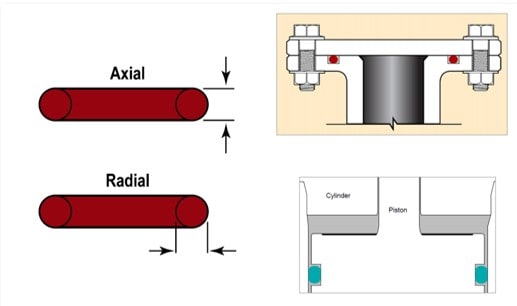
Figure 1 shows the difference between axial (top configuration) and radial (bottom configuration) compression. Radial compression can either be male or female, depending on whether the groove is cut in the piston or in the bore. This figure shows a male seal.
How do I know what cross section to pick?
The term “cross section” refers to the cross-sectional diameter of the seal (see figure 3). Determining the best value for the cross section is often a question of concern when designing a face seal. Parker offers 5 main cross section sizes, which are classified as different series O-rings. The industry standard AS568 is the starting point for our standard sizes. Given the wide range of sizes that we offer with our standard sizes and the ability to custom mold or extrude sizes that fall outside this range, this choice can be difficult to make.

Figure 2 shows a cross-sectional view of an O-ring. d1 is called the inner diameter (ID); d2 is referred to as the cross section (CS).
The obvious place to start is by asking if there are any design constraints that prevent a particular size cross section from being used. One of the main and obvious constraints that would impact the answer to this question is the available space for cutting the groove. Another possible constraint is whether the best inner diameter (ID) of an O-ring for the application/design is available in a particular cross section size. Parker’s smallest cross section seals have smaller IDs available than our largest cross-section seals, so they ID needed to seal a specific sized opening may only be available in certain cross sections. A less obvious constraint is compressive load force. A larger seal will require more force to be compressed to the same percentage as a smaller seal.
What is the Pressure Rating of a Face Seal?
Pressure rating is a tricky thing with O-rings as it is highly dependent upon the design of the hardware. The main failure mode that is tied to the value of the upper pressure limit of an application is extrusion. Extrusion in this sense is not the manufacturing process of forcing an elastomeric cord into a die to make a specific shape, but rather the forcing of a finished O-ring between the gap of mating hardware of a gland. Remember that an elastomer can be considered a highly viscous liquid, rather than a solid. So, under high pressure, an O-ring can flow into the mating hardware of its gland. Depending on how hard an O-ring is and what the clearance gap between mating hardware is the pressure limit of a particular design can be established.

Figure 3 shows the various stages of extrusion of an O-ring. These images are figures 1-4 through 1-7 of the Parker O-ring Handbook and can be found on page 1-3.
The below chart is taken from page 3-3 of the handbook and can be used to establish pressure limits for your design. The Limits for Extrusion Chart was originally intended to help establish pressure limits for radial sealing, as all radial seals require a gap between mating hardware, but many face seals are designed to have no gap between the mating hardware. If a face seal has no clearance gap (more often called a plate gap when using a face seal configuration) then it is very difficult to establish pressure limits without testing the application in question with the O-ring intended to be used. As stated in the handbook, there have been instances where a 70 durometer O-ring was used to reliably seal up to 200,000 psi, but obviously, this is far outside of what the limits for extrusion chart would recommend. If there is a plate gap present in a particular design, the maximum value of it should be used to determine pressure limits, derived from the limits for extrusion chart and functional testing.

Figure 4 shows the Limits for Extrusion chart, which is the best tool (aside from functional testing) to predict pressure ratings for a particular design. This chart is referred to as Figure 3-2 and can be found on page 3-3 of the Parker O-ring Handbook.
Following the Design Guide
Designing any groove is highly reliant on three main design parameters: stretch, squeeze and volume fill. The dimensions of the groove needed to lock these parameters within the ideal range across all design conditions will shift with the cross-section size that is selected, but to help Parker’s customers optimize their seal designs, a design guide specifying these values has been developed. This design guide on page 4-18 of the handbook is a critical resource in the process of designing face seals. Predetermined groove depths, widths, and diameters have been established in the chart and drawing on this page. The groove depths1 are based only on the cross-section size and the widths are dependent upon the cross section as well as the phase of the fluid being sealed (either liquid or gas).
The groove is then either dimensioned by the inner diameter or the outer diameter depending on whether the seal is pressurized externally or internally, respectively. External pressure occurs when the seal is exposed to fluid pressure on its OD, pushing it against the inner wall of the groove. Internal pressure is when the seal’s ID is exposed to the fluid pressure, pushing the seal into the outer wall of the groove. Ideally, the O-ring should not shift during pressurization; if it does, it can lead to small amounts of leakage. Under external pressure, the nominal groove ID should match the nominal (or mean) ID of the O-ring. The value of the nominal ID of a standard O-ring size can be found in the second column of Table 4-22 of the handbook, labeled “ID.” Likewise, under internal pressure, the nominal groove OD should match the nominal (or mean) OD of the O-ring. The nominal OD can also be found in fifth column of Table 4-22 of the handbook, labeled “Mean OD (Ref)” (see figure 4 for tolerances of groove ID or OD).
A good face seal design will also follow the surface finish recommendations, angles of the groove walls, and groove corner radii (both top and bottom). These details can be found in the image below (figure 4), taken from the handbook’s page 4-18.
Conclusion
While designing a face seal is certainly not the most complex challenge an engineer can face, it can be a difficult task to overcome without the right resources or proper training. Parker has developed a great library of resources that have become industry staples, not just for designing face seals, but all kinds of seals. Selecting the proper cross-section size is not just a challenge for face sealing, but also radial sealing. However, when broken down into the right steps, it can be accomplished with ease. Using the Limits for Extrusion chart, a pressure rating can be assigned to a face seal that has a plate gap. But with the unique ability to eliminate clearance gaps entirely, which is an invaluable benefit allowed by face seals, many designs will need to be functionally tested to determine pressure limits. With these two considerations addressed, an engineer can then determine the depth, width, and diameter of a groove.
This article was originally written by Logan Drawbaugh, applications engineer at Parker O-Ring & Engineered Seals Division


