Article re-posted with permission from Parker Hannifin Sealing & Shielding Team.
Original content can be found on Parker’s Blog.
This post is the second installment in a three-part series that describes the three main criteria for O-ring gland design: stretch, squeeze and volume fill. These three related components must be balanced to create the ideal conditions for O-ring sealing.
Understanding the basics of compression
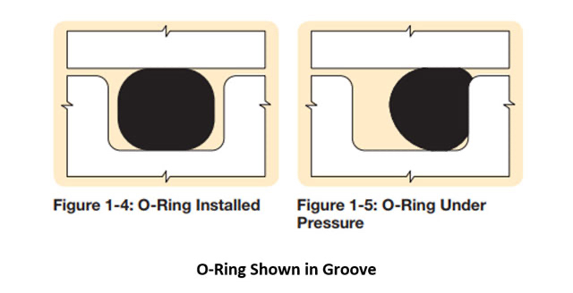
To form a robust seal, adequate compression or squeeze is a critical consideration. Compressing the seal energizes it, and the O-ring pushes back on the mating surfaces. This contact force between the O-ring and hardware creates a seal. Squeeze is calculated by the cross-section diameter minus the gland depth, all divided by the cross-section diameter. Note that in this calculation, the gland depth is the distance from the bottom of the groove to the mating surface. This accounts for any clearance gap.

Compression for different o-Ring sizes and gland designs
Parker’s recommended compression ranges have been empirically determined for various applications. Less squeeze is recommended for dynamic applications, while static applications require more squeeze. The O-Ring handbook contains design charts with recommended squeeze ranges for face seals, static or reciprocating radial seals and some specialty applications such as dovetails, crush grooves and rotary grooves. Parker’s online design tools, the O-ring selector and Mobile InPhorm calculate the compression for your design and compares it to the compression range for the particular application. The recommended compression range is dependent on the size of the seal and the groove type.

Failure modes related to compression
Some design challenges can be pitfalls in compression that can compromise the seal. Sufficient compression helps to maintain the longevity of the seal as well as providing sealing capability. Over compression can lead to premature compression set, be difficult to install or even rupture the seal. Too little compression can also result in compression set and/or result in leakage. O-Rings should be evenly compressed around the sealing surface. Sideloading or eccentricity should be prevented as much as possible because it can cause uneven compression set on the seal and can affect sealing ability and life. Face seals should be compressed consistently around its surface with no gapping. In application, there should be no sharp corners contacting the seal that may damage the seal.
Compression set
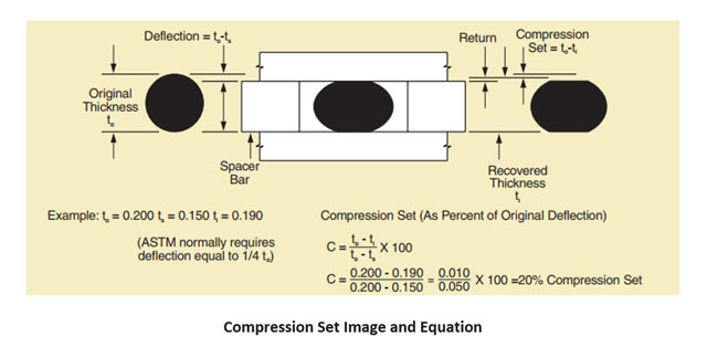
Compression set is both a laboratory test and a failure mode. Compression set is when a seal does not recover from its compressed state to its original shape after being released from loading. Compression set from a testing perspective is generally determined in air aging and reported as the percent of deflection by which the elastomer fails to recover after a fixed time under specified squeeze and temperature. Zero percent is the best-case scenario and indicates no relaxation has occurred. For an O-ring, zero percent compression set will have a round cross section. On the other hand, 100 percent compression set indicates total relaxation; the seal just contacts mating surfaces but no longer exerts a force against those surfaces. The compression set seal, when removed from the hardware, will appear flat and set in its compressed state.

Many factors can contribute to compression set, and it is one of the most common o-ring failure modes. Compression set does not always result in failure, and some degree of compression set is normal and seen in nearly every application. An O-ring may continue to seal after taking 100 percent compression set, provided the temperature and system pressure remain steady, and no motion or force causes a break in the line of seal contact. High temperature exposure, inherent material properties and chemical exposure can all contribute to compression set. Larger cross sections tend to resist compression set better than smaller cross sections. Some materials are considered more compression set resistant but remember that a good balance of all physical properties is usually necessary for optimum seal performance.
Compression and installation force
Compressing the seal requires closure force from the hardware. The required compression force increases with higher squeeze, larger seal size and higher durometer materials. Inherently, some materials are easier to compress than others. Silicones and fluorosilicones require the least compression force, while FKM materials require the most compression force, even at the same durometer.
To decrease compression force and installation force, consider selecting a material with a lower durometer and/or modulus and decrease the squeeze. For radial application installation force, design a lead in chamfer that is between 15-20 degrees and lubricate the seal. For low closure force requirements in face seal applications, there may be an opportunity to use a hollow profile, which further decreases the installation force. We recommend selecting hardware that can provide uniform sealing surfaces with no warping.


