Gallagher recently released its Expansion Joint Design Guide, now available for download on our site. This design guide takes an in-depth look at elastomeric, metal, and flue duct expansion joints. The excerpt below is a section of our Expansion Joint Design Guide focusing on types of elastomeric joint installation, pipe layouts, and joint troubleshooting. To download the entire guide, visit our Resources Page, or click on the image to the right.
Preparation
Check Service Range
Double check expansion joint performance limits against anticipated operating conditions
Check total joint deflection—alter as needed to reduce deflection to correct range
Anchor lines
Check Location
Proper location is usually close to main anchoring point
Install pipe guide(s) for proper alignment
Joint should absorb pipeline expansion / contraction between fixed anchor points
Check Cover
Check outside joint cover for damage
Cover will keep harmful materials from penetrating joint carcass
Check Alignment
Alignment should be 0.125” (3.2 mm) or less
If 0.125” (3.2mm) must be exceeded, use a special offset joint
Check Support
Weight must not be carried by joint
Support with hangers or anchors
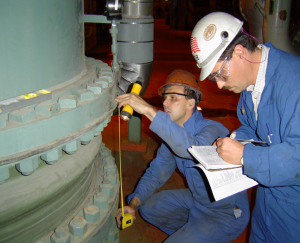
Check Flanges
Clean all mating flanges
Do not gouge or mutilate surfaces during cleaning
Carefully examine used parts for smoothness
Installation
Apply Lubricant
On elastomeric joints only, not required with all PTFE- or FEP-lined joints
Coat rubber faces with graphite in water, or glycerine, to prevent joint adherence to pipe flanges
Insert Bolts from Arch Side
On elastomeric joints only, not necessary with PTFE joints/couplings with threaded holes
Set bolt heads adjacent to arch
Tighten bolts
Elastomeric joints only, tighten gradually and equally, alternating around flange
Edges of joint must bulge slightly at flange O.D.
Check tightness
Within one week after application, then periodically
In hot or cold water systems during cyclical changes
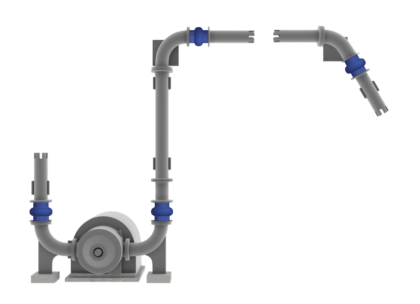
Typical Piping Layout
Pipe is anchored to support it and to stabilize the expansion joint. Pipe leg anchor should be used for horizontal suction piping, while an “H-Frame” should be used to anchor vertical discharge where end thrust causes lateral motion and potentially excessive misalignment.
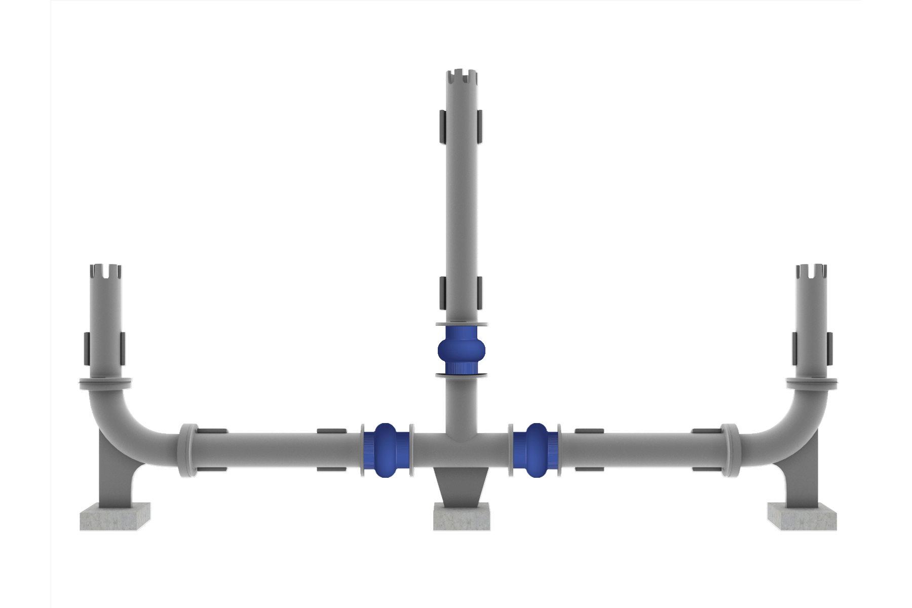
Proper Use of Anchors in Branch Connections
Anchors should be bolted to floor and welded to pipe before installation of expansion joint. All anchors and guides should be installed according to EJMA standards.
General Precautions for Elastomeric Joints
Use proper care breaking seal
Drive flanges apart gently with wooden wedges
Bring insulation only to pipe flange—do not insulate over or around joint
Covering joints may make leak detection difficult
Insulation could restrict joint movement or cause overheating
Store in cool, dry, dark area
Do not rest on flange edges
Carefully protect joints near welding operations
Never install spool-type joints next to flangeless check valves or butterfly valves
Install only against full-face metal flanges or damage/leakage could result; restrictions also apply to raised face or any non-full face flange
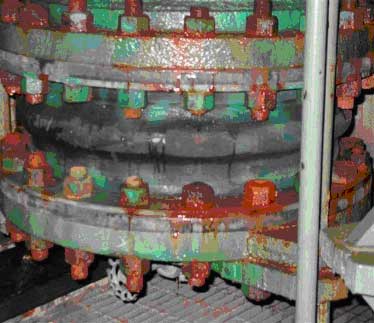
Troubleshooting
Flange Leakage
Check bolt tightness
Check mating flange surface area for:
Grooves
Scratches
Distorted areas
Over-extension may indicate need for control units
Liquid weeping from bolt holes
Check tube portion of joint for leaks; replace if necessary
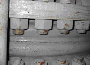
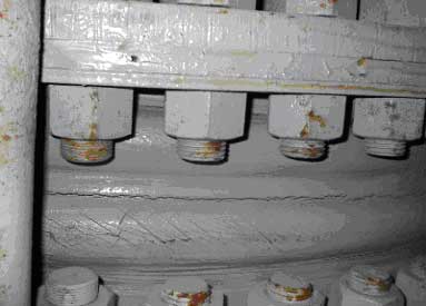
Cracking at base of arch or flange
Check installed face-to-face dimensions for over-extension or over-compression
Check for proper pipe alignment: must not exceed 0.125” (3.2mm)
Excessive ballooning of arch
Indicates distortion/deterioration of joint strengthening members, or excessive system pressure