o-rings
- July 06, 2021
GUARDIAN® is Air Sentry's industry leading breather series. The GUARDIAN's casing is constructed from Tritan®, a patented material highly resistant to impact and chemicals with a broad range of operating temperatures. These unique features equate to a longer life for your breather and your equipment.
GUARDIAN's modular construction and optional add-on features allow you to customize each Guardian model to your specific application requirements. From the isolation check valve, to its stackable design, from its wash-down cap, or its compound indicating gauge, to the high-capacity HEPA filter, the GUARDIAN will last longer and reduce downtime giving you the flexibility you need to protect your industrial assets.
- June 03, 2021
Elastomers are a high molecular weight polymer that exhibits little plastic flow, and has a rapid recovery from an extending or compressing force. Elastomers are produced naturally as gum rubber on commercial rubber plantations or manufactured synthetically. Today, more than 32 synthetic rubbers are known.
In Part 2 of our webinar series, Benjamin Mell, Regional Sales Manager at Gallagher Fluid Seals will elaborate on the most common types of elastomers used in o-ring applications. He will discuss their performance characteristics, application details, and pros vs. cons.
- May 13, 2021
O-rings are the most common sealing product in the world. An O-ring is a versatile solution that will effectively seal every time, assuming that basic design parameters are followed. It is also an inexpensive sealing solution compared to other products. An O-ring should always be considered for a seal application due to its low price and availability.
This blog and is the first in a multi-part video webinar series on the basics of o-rings.
- July 29, 2020
Spring-energized metal seals provide numerous advantages in oil and gas applications, including but not limited to MWD and LWD tools, couplings, subsea compressors, enclosures/vessels, christmas trees, electronic submersible pumps and flowmeters. Extreme operating pressures and temperatures, together with more difficult resource recovery, zero tolerance for failure and environmental concerns, are placing unprecedented demands on this equipment.
Traditionally this industry has used solid machined seals that provide high compression loads but lack resilience. They also tend to have relatively high rates of leakage over time as flanges deteriorate. Recent advances in metal seal technology provide controlled compression, high resilience and reduced leakage.
Background
- June 23, 2020
Article re-posted with permission from Parker Hannifin Sealing & Shielding Team.
Original content can be found on Parker’s Website and was written by Dan Ewing, senior chemical engineer, Parker Hannifin O-Ring & Engineered Seals Division.
Compressive Stress Relaxation (CSR) is a means of estimating the service life of a rubber seal over an extended period of time. As such, it can be thought of as the big brother of compression set testing. Rather than measuring the permanent loss of thickness of a compressed rubber specimen as is done in the compression set, CSR testing directly measures the load force generated by a compressed specimen and how it drops over time. In part 1 of our blog series, we will explore the theory of CSR testing, common test methods, and how CSR differs from compression set testing.
Theory of Compressive Stress Relaxation Testing
To understand the value of CSR testing and how it differs from compression set testing, it is helpful to return to the basic theory of how a rubber seal functions. In a standard compressed seal design, a rubber seal is deformed between two parallel surfaces to roughly 75% of its original thickness. Because the material is elastic in nature, the seal pushes back against the mating surfaces, and this contact force prevents fluid flow past the seal, thus achieving a leak-free joint. Over time, the material will slowly (or perhaps not so slowly) relax. The amount of force with which the seal pushes against the mating surfaces will drop, and the seal will become permanently deformed into the compressed shape. In compression set testing, the residual thickness of the specimen is measured, and it is assumed that this residual thickness is valid proxy for the amount of residual load force generated by the compressed seal. In CSR testing, the residual load force is measured directly.
In practice, compressive stress relaxation results are typically presented very differently from compression set results. In CSR testing, it is common to see multiple time intervals over a long period of time (3,000 hours or more of testing), thus allowing a curve to be created (see Figure 1). In practice, however, specifications are written such that only the final data point has pass/fail limits. In compression set testing, it is common to see a single data point requirement with a single pass/fail limit. Multiple compression set tests can be performed to create a curve, but this is almost always done for research purposes rather than for specification requirements. In most cases, compounds that excel in compression set resistance also demonstrate good retention of compressive load force over time. However, there are exceptions.
Figure 1: Typical CSR curve. These results display a fluorocarbon seal material immersed in engine oil at 150°C. - June 05, 2020
Article re-posted with permission from Parker Hannifin Sealing & Shielding Team.
Original content can be found on Parker’s website and was written by Dorothy Kern, applications engineering lead, Parker O-Ring & Engineered Seals Division.
There are 400+ standard O-ring sizes, so which is the right one for an application? Or maybe you are wondering if one O-ring thickness is better than another. This short article will walk through some of the design considerations for selecting a standard, commercially available O-ring for an application.
Design Considerations
Hardware geometry and limitations are the first consideration. A traditional O-ring groove shape is rectangular and wider than deep. This allows space for the seal to be compressed, about 25% (for static sealing), and still have some excess room for the seal to expand slightly from thermal expansion or swell from the fluid. Reference Figure 1 as an example. Once the available real estate on the hardware is established, then we look at options for the O-ring inner diameter and cross-section.
AS568 Sizes
From a sourcing perspective, selecting a commercially available O-ring size is the easiest option. AS568 sizes are the most common options available both through Parker and from catalog websites. A list of those sizes is found in a couple of Parker resources including the O-Ring Handbook and the O-Ring Material Offering Guide. They are also listed here. The sizes are sorted into five groups of differing cross-sectional thicknesses, as thin as 0.070” and as thick as 0.275”, shown in Table 1 below.
- March 25, 2020
Article re-posted with permission from Parker Hannifin Sealing & Shielding Team.
Original content can be found on Parker’s Website and was written by William Pomeroy, applications engineer, Parker O-Ring & Engineered Seals Division.
As mentioned in part one of Parker's seal failure blog series, O-ring and seal failures are often due to a combination of failure modes, making root cause difficult to uncover. It's important to gather hardware information, how the seal is installed, application conditions, and how long a seal was in service before starting the failure analysis process. In part 1, compression set, extrusion and nibbling, and spiral failure were discussed. In part 2 of Parker's series, they will review four other common failure modes to familiarize yourself with before diagnosing a potential seal failure in your application.
Rapid Gas Decompression
Rapid gas decompression (commonly called RGD, or sometimes explosive decompression (ED)) is a failure mode that is the result of gas that has permeated into a seal that quickly exits the seal cross section, causing damage.
Detection of this failure mode can be difficult, as the damage does not always show on the exterior. When the damage is visible, it can look like air bubbles on out the outside, or perhaps a fissure that has propagated to the surface. The damage may also be hidden under the surface. If the seal is cut for a cross section inspection, RGD damage will look like fissures in the seal that may or may not propagate all the way to the surface.
Parker’s guidance as to how to avoid this failure mode is: 1) Keep the depressurization rate lower than 200 psi per minute. If this cannot be achieved, they would suggest 2) RGD resistant materials. Parker offers these RGD resistant options from the HNBR, FKM, EPDM, and FFKM polymer families.
Abrasion
Abrasion damage is the result of the seal rubbing against a bore or shaft, resulting in a reduction of cross sectional thickness due to wear. As the seal wears, it has the potential to lose compression on the mating surface. This wear is compounded by the fact that dynamic applications already have lower compression recommendations.
To reduce risk for this failure mode, it requires consideration during design and seal selection. The surface finish and concentricity of the hardware will be very important considerations. A smooth surface results in less friction (suggest 8 to 16 RMS), which in turn results in less wear. Increasing the durometer of the seal material helps resist wear, and there are also internally lubricated materials that could be employed. If the application is high temperature, one should consider the impacts of thermal expansion on the elastomer being used. The thermal expansion increases contact pressure, which would increase friction / wear.
- October 22, 2019
Article re-posted with permission from Parker Hannifin Sealing & Shielding Team.
Original content can be found on Parker’s Website and was written by Nathaniel Reis, Applications Engineer for Parker O-Ring & Engineered Seals Division.
In our semiconductor entry from last month, we noted that lowering the cost of ownership is a multi-faceted goal. We discussed how one of the areas for potential improvement
- September 17, 2019
Article re-posted with permission from Parker Hannifin Sealing & Shielding Team.
Original content can be found on Parker’s Website and was written by Nathaniel Reis, applications engineer, Parker O-Ring & Engineered Seals Division.
When it comes to semiconductor fabrication processes, reducing the cost of ownership is a multi-faceted goal approached from a variety of angles. Tool engineers and equipment technicians take pride in their ability to identify factors that limit tool uptime. One constant headache they face is the mechanical failure
- May 21, 2019
Article re-posted with permission from Parker Hannifin Sealing & Shielding Team.
Original content can be found on Parker’s Website and was written by Nathan Wells, Application Engineer, Parker Engineered Polymer Systems Division.
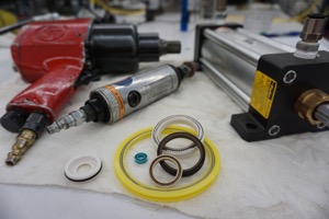
My grandpa used to have a rusty, old air compressor in his shop. As a child, when my siblings and I would visit him, he’d use it to power air wrenches, grinders, and inflate flat soccer balls for us. I noticed it had a port labeled “ADD OIL DAILY” that was covered in the same thick layer of greasy dust as all the other unused junk in his shop. Knowing my grandpa, if asked about adding oil he probably would have said, “Oil is expensive. That’s how the companies get ya!” The compressor’s seals leaked so badly, you could hear the hissing even over the loud motor. I was certain one day it would explode.
Pneumatic tools are common in factories, tool shops, and DIY garages around the world. Using compressed air for power is convenient, simple, and — when maintained properly — safe and efficient. However, air treatment costs can add up fast. Traditional rubber seals used in air tools require clean, low moisture, compressed air with the proper amount of lubrication added. Good Filter/Regulator/Lubricator systems (FRLs) cost as much as the tools themselves! So, what would happen if we didn’t have to provide pristine air?
Today we have the technology to create seals for tools which don’t require daily or even yearly upkeep. You’ll find these tools labeled “maintenance-free,” which sounds great to the guy responsible for maintenance. It sounds even better to the guy paying for maintenance … and to engineers designing tools who want to keep warranty costs down.
Seal materials for dry running
Early pressure seals were made out of leather. My grandpa’s compressor probably wasn’t that old, but even since his time, we’ve come a long way.
When I’m asked for seal recommendations in totally dry-running applications, my mind clicks to a material called PTFE (chemical name polytretrafluoroethylene). Most people know PTFE by the brand name Teflon® and are familiar with its use when applied to cookware as a high temperature, slippery, non-stick coating.
PTFE is a semi-hard plastic which feels slick to the touch thanks to its low friction properties. It’s considered self-lubricating because it leaves micro deposits on the sealing surface and reduces friction after just a few strokes. Because of this, it’s good for high-speed sealing and can operate completely dry.
By adding fillers to PTFE, seal manufacturers can tailor materials for greater suitability in meeting performance requirements for a wide range of conditions. String-like additives including fiberglass and carbon fiber increase pressure rating, wear resistance and seal life. Dry lubricant-type additives such as graphite or molybdenum disulfide (MoS2) further increase a seal’s ability to run without lubrication, and at higher speeds and pressures. In pneumatic medical, pharmaceutical, and food processing systems, clean grade mineral-based strengtheners may be used as additives.
PTFE seals for dry running equipment are available in several profile configurations: