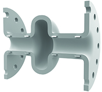
Expansion Joints
-
October 15, 2019
A flexible choice can adapt to permanent misalignment, preventing future damage.
Keeping aging facilities and equipment maintained is an ever-changing task that can jeopardize the goal of maximizing uptime. Years of thermal cycling, vibration or foundation settling can disorient piping or pumps. Piping engineers will use rubber expansion joints to account for these types of challenges in a rigid piping system. Permanent misalignment can set in after years of operation. The original-size expansion joint could no longer be the best fit when it comes time to replace.
Replacing a permanently misaligned expansion joint connection with the original part could lead to reduced service life and/or missed expectations of the new expansion joint. Determining the best way to accommodate this when it comes time to replace the existing expansion joint can have long-term effects on reliability. Since the original components may not fit in the newly disoriented flange connection, they are limited in their reliability.
Types of Customization & Benefits
Expansion joints are designed to withstand the pressure retention of rigid pipes, yet be flexible and absorb misalignment induced in these systems. However, there are limits to exactly how much flexibility can be absorbed before damage occurs. Using this flexibility to connect two misaligned pipe flanges will take away from how much movement can be absorbed during the actual operational period when the system is running.
Attempting to retrofit a standard-size expansion joint to connect a misaligned pipe connection can put excessive stress on the component and could lead to a shorter operational service life. For this reason, the Fluid Sealing Association (FSA) recommends no greater than ±1/8-inch misalignment of the pipe flanges during installation. Depending on the severity of misalignment, it can be advantageous to implement custom expansion joints to minimize the stresses that cause these joints to fail or become damaged during installation.
Maintenance crews can also benefit by having a component that will fit precisely. Concerns for safety are present when attempting to put enormous pressure to compress, elongate or offset the joint so it will fit in place.
Custom expansion joints, made-to-fit, provide long-term dependability and can be designed in many orientations. To prevent overexertion, expansion joints are often constructed to connect nonstandard distances between pipe flanges. Other modes of misalignment can connect pipe flanges that are no longer centered.Face-to-Face Tailoring
Image 1. Stress area stretched axially during installation Years of cycling, wear and other factors can contribute to the disorientation of a particular pipe connection. The length of an expansion joint, a dimension commonly referred to as face-to-face, bridges the gap between two parallel pipe flanges. A common industry problem is created when foundations settle and piping support structures transition lower than where it was originally constructed (Image 1). Expansion joints are designed to account for this, but choosing the correct replacement will make the difference between continued reliable service life or system failure.
Stretching an expansion joint to fit the changed flange connection often results in immediate damage that is only sometimes visual to the naked eye. A stress point on the outer cover of the expansion joint will usually become visible at the transition corner between the flat portion and the base of the arch in the form of a crack. The severity of cracking, elongation and settling will be aggravated when pressure in the pipeline is turned on.
Depending on nominal pipe size, industry standards will include standard face-to-face sizes of 6, 8, 10 or 12 inches, according to the FSA. When a standard 6-inch face-to-face joint is removed, the length between flanges could have been elongated to 7 inches or more. Many expansion joint consumers are not aware of the capability to build the expansion joint to the required nonstandard 7-inch face-to-face since it is not a standard offering. Building the replacement expansion joint to the nonstandard 7-inch face-to-face will eliminate any initial stress imposed on the joint.
Lateral offset expansion joint. and Angular offset expansion -
January 29, 2019
Expansion Joint Control Units
Elongation settings are a vital factor to assembly effectiveness.
It is no secret that one of the greatest demands for an expansion joint is the expectation to serve a long, leak-free life with little-to-no maintenance. Once installed, these flexible rubber connectors should require little attention. The preservation of this investment (and one’s sanity) can be maximized with an in-depth overview of how control units can prevent a new expansion joint from being overstressed.
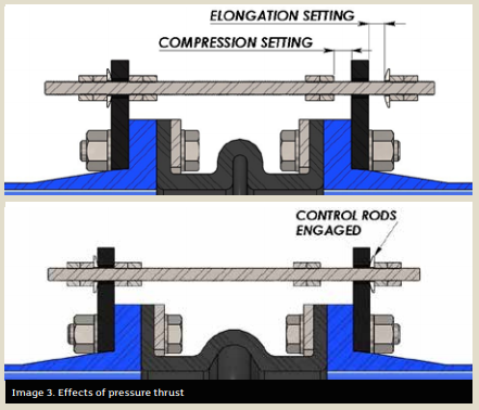
The purpose of a control unit is to act as a safety device against excessive movement resulting from pressure thrust. A typical control unit assembly is comprised of threaded rods, steel gusset plates, nuts and washers (see Images 1 and 2).
The usage of control units with an expansion joint is always beneficial; pressure spikes during a system upset can cause uncontrolled surges through the expansion joint. This is a prime example of how valuable it is to have control units installed to protect these rubber assets from damage.
Methods to the Madness
A common misconception about control units is that they are designed to support the weight of pipe members or act as a substitute for adequate mounting. They are not. The sole purpose of a control unit is to allow the expansion joint to move freely within a specific range of movement while preventing the joint from being overstretched from pressure thrust forces.
The control units in no way impede the joint from performing its other duties beyond movement (vibration absorption, cycling or compensation for misalignment). The few extra steps needed to install the control units with the expansion joint could pay notable dividends in the long run.
Pressure thrust plays a huge role in how an expansion joint functions. While under pressure, the forces acting on the inside walls of the expansion joint actually cause the joint to swell and elongate. In the real world, an expansion joint is held comfortably between two pipe flanges, which in most cases are restrained by a pump lagged to the floor or mounted to a structural beam. Although it may not be apparent to the naked eye, once the expansion joint sees pressure, it produces a thrust force that acts axially on both pipe flanges.
Theoretically, what would be the result if the expansion joint was unrestrained on each end while pressurized?
Without fixed ends, the pressure thrust would force the joint to elongate without bounds.
Most useful in high pressure applications, the control rods will engage with the gusset plates once a pre-specified amount of growth for the expansion joint has been reached, restricting the joint from stretching any further. At this point, the control rods are absorbing any additional thrust acting on the pipe flange, thus limiting the amount of stress that is exerted onto adjoining equipment.
The design theory for sizing control unit hardware is based on the pressure thrust. Nominal inside diameter (ID) and arch geometry of the expansion joint are key drivers for calculating the thrust force that will be applied to the pipe at maximum line pressure. Per
industry standards set by the Fluid Sealing Association (FSA), both control rods and gusset plates are designed to withstand no more than 65 percent of the yield strength of the material.
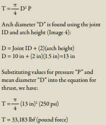
Magnitude of the pressure thrust can be calculated by knowing the internal pressure and the effective area of the expansion joint. Effective area is found using the arch diameter of the expansion joint, which takes into account the size of the arch.
For example, we can calculate the resulting pressure thrust for a 10-inch ID expansion joint using an arch height of 1.5 inches that is rated for a maximum pressure of 250 pounds per square inch (psi).
The equation for pressure thrust “T” is:
These design limitations based around yield stress are the reasons why some control units made from lower yield strength stainless steel contain thicker components or more rods per set than the standard carbon steel control units.
Installation & Inspection
For a control unit assembly to be effective, rod positioning and elongation settings are critical during installation. Each control rod should be evenly spaced around the flange to best distribute the load. Elongation settings (see Image 5) are often overlooked, yet are a vital factor to ensure the control units fulfill their intended use.
Every expansion joint comes with movement ratings based on arch size, configuration and number. These movement design ratings of the expansion joint are critical pieces of information that are absolutely required during the installation of control units. The general rule of thumb is the gap between the gusset plate and the nut should be adjusted to match the joint’s elongation rating.
Having this information at hand during installation is great, but what about the existing control units currently in operation? Visual inspections of these components are a basic task that goes a long way toward extending the life of the joint.
Here are the top 4 anomalies to look for when performing a field inspection:
-
December 18, 2018
The ABRA-LINE™ family of products was developed for highly abrasive applications typically found in the power generation, fertilizer, mining and chemical industries. These may include flue gas desulphurization systems, phosphate mining, dry bulk power transfer systems, tailings and slurry applications. Our proprietary urethane formula was designed to reduce wear and extend
service life.Style 404 Expansion Joints are specially designed for full vacuum abrasive service applications. The tube material is a proprietary urethane formulation. Style 404 can be constructed as a single or multiple arch design. It can also connect pipe flanges in concentric or eccentric tapers, to join piping of unequal diameters.
Case Study: Chemical Processing
Industry
Chemical ProcessingObservation
A stainless hosing was used and would continuously fail due to abrasion on the leading edge of the hose. The hosing would last for 3 to 6 months before replacement. -
November 06, 2018
Gallagher Fluid Seals recently added the Rubber Expansion Joint Surveys & Failure Analysis white paper to our Resources page. This white paper discusses the importance of inspecting your plant’s expansion joints. Proper design and maintenance of rubber expansion joints plays a major role in the overall preservation and lifespan of a piping system.
It will also discuss failure analysis of rubber expansion joints and some of the leading causes of joint failure.
Below is an except from the white paper, discussing failure analysis of rubber expansion joints, and what it can tell you about the overall health of your piping system.
Failure Analysis
There are perceptible warning signs when an expansion joint is failing:
- Arch inversion indicating a system vacuum that has exceeded the joint’s specified expansion value.
- Cracking at the base of the arch, which indicates the joint has been over-elongated and should be replaced with one of the proper length.
- Ply separation on the outside of the cover. This is an indication the joint has been subjected to excessive movement.
- Leakage due to over-expansion, mating flange surface issues, or poor installation practices, especially (but not limited to) bolt tightness.
- Ballooning of arch, which indicates excessive system pressure.
-
September 27, 2018
Gallagher Fluid Seals recently added the Rubber Expansion Joint Surveys & Failure Analysis white paper to our Resources page. This white paper discusses the importance of inspecting your plant's expansion joints. Proper design and maintenance of rubber expansion joints plays a major role in the overall preservation and lifespan of a piping
-
September 28, 2017
In July, Gallagher released its Expansion Joint Design Guide, now available for download on our site. This design guide takes an in-depth look at elastomeric, metal, and flue duct expansion joints. The excerpt below is a section of our Expansion Joint Design Guide focusing on types of flue duct expansion joints. To download the entire guide, visit our Resources Page, or click on the image to the right.
Flue Duct Expansion Joints
Used to manage air and gas handling systems, flue duct expansion joints are most widely utilized in the Power Generation, Industrial & Institutional industries:
-
August 24, 2017
Gallagher recently released its Expansion Joint Design Guide, now available for download on our site. This design guide takes an in-depth look at elastomeric, metal, and flue duct expansion joints. The excerpt below is a section of our Expansion Joint Design Guide focusing on types of metal expansion joints. To download the entire guide, visit our Resources Page, or click on the image to the right.
Much like elastomeric expansion joints, metal expansion joints are used to preserve the integrity of a piping system where the piping is subject to changes in temperature, pressure, vibration, compression, extension, cyclical movements or movements required by usage.
Oftentimes, metal expansion joints are used when an elastomeric joint simply cannot handle the extreme conditions - applications where high temperature, large temperature range, or high pressure exists. Generally, metal expansion joints can be used from -450°F to +2000°F, depending on the metallurgy, and can also handle pressures from full vacuum to 3,000psi.
Metal Expansion Joint Components
Though customized and intricate expansion joints can be manufactured for a variety of specialized applications, there are four basic designs that are most commonly used:
Basic Bellows
A bellows can be supplied without end fittings for field installation. The skirt, or straight portion at each end of the bellows, can be sized to fit a flange or pipe. Skirt length can vary depending on your needs and should be specified when ordered.
Unrestrained Single
An unrestrained single expansion joint is best used by piping systems which are equipped with proper guides and anchors to absorb axial, angular, and a small amount of lateral movement.
-
August 08, 2017
Gallagher recently released its Expansion Joint Design Guide, now available for download on our site. This design guide takes an in-depth look at elastomeric, metal, and flue duct expansion joints. The excerpt below is a section of our Expansion Joint Design Guide focusing on types of elastomeric joint installation, pipe layouts, and joint troubleshooting. To download the entire guide, visit our Resources Page, or click on the image to the right.
Preparation
Check Service Range
- Double check expansion joint performance limits against anticipated operating conditions
- Check temperature, pressure, vacuum recommendations
- Check total joint deflection—alter as needed to reduce deflection to correct range
- Anchor lines
Check Location
- Proper location is usually close to main anchoring point
- Install pipe guide(s) for proper alignment
- Joint should absorb pipeline expansion / contraction between fixed anchor points
-
July 25, 2017
Gallagher recently released its Expansion Joint Design Guide, now available for download on our site. This design guide takes an in-depth look at elastomeric, metal, and flue duct expansion joints. The excerpt below is a section of our Expansion Joint Design Guide focusing on types of elastomeric joints and types of pipe movement. To download the entire guide, visit our Resources Page, or click on the image to the right.
The basic purpose of an expansion joint is to absorb movement and vibration in a rigid piping system, being built to expand, contract, and adjust without straining or breaking the piping or ducting on either side. They are specially engineered to handle movements due to thermal expansion, vibrations of pumps, and misalignments due to installation tolerances, while also being resistant to the process conditions and the external influences of the application.
Types of Expansion Joints
- Fabric and rubber construction
- Reinforced with metal/wire rings
- Full-face flanges integral with joint body
- Flanges drilled to companion bolt pattern
- Gaskets not required
- Offset available
-
June 29, 2017
An expansion joint can relieve stress in piping systems and prevent flange gaskets from being crushed. But which expansion joint is best for your specific application? Let us first describe the two types of expansion joints:
Rubber — a flexible connector fabricated of natural and/or synthetic elastomers and fabric and, if necessary, internal metallic reinforcements designed to provide stress relief in piping systems due to thermal movements and mechanical vibration.
Metal — a flexible element (bellows) constructed of relatively thin gauge material (generally stainless steel) designed to absorb mechanical and thermal movements expected in service.
Advantages: Metal Expansion Joints
Temperature
Rubber joints with standard construction and materials have an upper range to 230°F. Most manufacturers, however, can offer special constructions up to 400°F. Metal expansion joints do offer a far greater range, from -420°F to +1800°F. However, working pressures are reduced at elevated temperatures.