o-rings
-
June 23, 2020
Article re-posted with permission from Parker Hannifin Sealing & Shielding Team.
Original content can be found on Parker’s Website and was written by Dan Ewing, senior chemical engineer, Parker Hannifin O-Ring & Engineered Seals Division.
Compressive Stress Relaxation (CSR) is a means of estimating the service life of a rubber seal over an extended period of time. As such, it can be thought of as the big brother of compression set testing. Rather than measuring the permanent loss of thickness of a compressed rubber specimen as is done in the compression set, CSR testing directly measures the load force generated by a compressed specimen and how it drops over time. In part 1 of our blog series, we will explore the theory of CSR testing, common test methods, and how CSR differs from compression set testing.
Theory of Compressive Stress Relaxation Testing
To understand the value of CSR testing and how it differs from compression set testing, it is helpful to return to the basic theory of how a rubber seal functions. In a standard compressed seal design, a rubber seal is deformed between two parallel surfaces to roughly 75% of its original thickness. Because the material is elastic in nature, the seal pushes back against the mating surfaces, and this contact force prevents fluid flow past the seal, thus achieving a leak-free joint. Over time, the material will slowly (or perhaps not so slowly) relax. The amount of force with which the seal pushes against the mating surfaces will drop, and the seal will become permanently deformed into the compressed shape. In compression set testing, the residual thickness of the specimen is measured, and it is assumed that this residual thickness is valid proxy for the amount of residual load force generated by the compressed seal. In CSR testing, the residual load force is measured directly.
In practice, compressive stress relaxation results are typically presented very differently from compression set results. In CSR testing, it is common to see multiple time intervals over a long period of time (3,000 hours or more of testing), thus allowing a curve to be created (see Figure 1). In practice, however, specifications are written such that only the final data point has pass/fail limits. In compression set testing, it is common to see a single data point requirement with a single pass/fail limit. Multiple compression set tests can be performed to create a curve, but this is almost always done for research purposes rather than for specification requirements. In most cases, compounds that excel in compression set resistance also demonstrate good retention of compressive load force over time. However, there are exceptions.
Figure 1: Typical CSR curve. These results display a fluorocarbon seal material immersed in engine oil at 150°C. -
June 05, 2020
Article re-posted with permission from Parker Hannifin Sealing & Shielding Team.
Original content can be found on Parker’s website and was written by Dorothy Kern, applications engineering lead, Parker O-Ring & Engineered Seals Division.
There are 400+ standard O-ring sizes, so which is the right one for an application? Or maybe you are wondering if one O-ring thickness is better than another. This short article will walk through some of the design considerations for selecting a standard, commercially available O-ring for an application.
Design Considerations
Hardware geometry and limitations are the first consideration. A traditional O-ring groove shape is rectangular and wider than deep. This allows space for the seal to be compressed, about 25% (for static sealing), and still have some excess room for the seal to expand slightly from thermal expansion or swell from the fluid. Reference Figure 1 as an example. Once the available real estate on the hardware is established, then we look at options for the O-ring inner diameter and cross-section.
AS568 Sizes
From a sourcing perspective, selecting a commercially available O-ring size is the easiest option. AS568 sizes are the most common options available both through Parker and from catalog websites. A list of those sizes is found in a couple of Parker resources including the O-Ring Handbook and the O-Ring Material Offering Guide. They are also listed here. The sizes are sorted into five groups of differing cross-sectional thicknesses, as thin as 0.070” and as thick as 0.275”, shown in Table 1 below.
-
March 25, 2020
Article re-posted with permission from Parker Hannifin Sealing & Shielding Team.
Original content can be found on Parker’s Website and was written by William Pomeroy, applications engineer, Parker O-Ring & Engineered Seals Division.
As mentioned in part one of Parker's seal failure blog series, O-ring and seal failures are often due to a combination of failure modes, making root cause difficult to uncover. It's important to gather hardware information, how the seal is installed, application conditions, and how long a seal was in service before starting the failure analysis process. In part 1, compression set, extrusion and nibbling, and spiral failure were discussed. In part 2 of Parker's series, they will review four other common failure modes to familiarize yourself with before diagnosing a potential seal failure in your application.
Rapid Gas Decompression
Rapid gas decompression (commonly called RGD, or sometimes explosive decompression (ED)) is a failure mode that is the result of gas that has permeated into a seal that quickly exits the seal cross section, causing damage.
Detection of this failure mode can be difficult, as the damage does not always show on the exterior. When the damage is visible, it can look like air bubbles on out the outside, or perhaps a fissure that has propagated to the surface. The damage may also be hidden under the surface. If the seal is cut for a cross section inspection, RGD damage will look like fissures in the seal that may or may not propagate all the way to the surface.
Parker’s guidance as to how to avoid this failure mode is: 1) Keep the depressurization rate lower than 200 psi per minute. If this cannot be achieved, they would suggest 2) RGD resistant materials. Parker offers these RGD resistant options from the HNBR, FKM, EPDM, and FFKM polymer families.
Abrasion
Abrasion damage is the result of the seal rubbing against a bore or shaft, resulting in a reduction of cross sectional thickness due to wear. As the seal wears, it has the potential to lose compression on the mating surface. This wear is compounded by the fact that dynamic applications already have lower compression recommendations.
To reduce risk for this failure mode, it requires consideration during design and seal selection. The surface finish and concentricity of the hardware will be very important considerations. A smooth surface results in less friction (suggest 8 to 16 RMS), which in turn results in less wear. Increasing the durometer of the seal material helps resist wear, and there are also internally lubricated materials that could be employed. If the application is high temperature, one should consider the impacts of thermal expansion on the elastomer being used. The thermal expansion increases contact pressure, which would increase friction / wear.
-
October 22, 2019
Article re-posted with permission from Parker Hannifin Sealing & Shielding Team.
Original content can be found on Parker’s Website and was written by Nathaniel Reis,
-
September 17, 2019
Article re-posted with permission from Parker Hannifin Sealing & Shielding Team.
Original content can be found on Parker’s Website and was written by Nathaniel
-
May 14, 2019
Seals are one of the most important components in many medical devices. While small in cost, seals for medical devices have a profound affect on the function of said device and the outcome of a medical procedure.
Engineered sealing solutions have advanced to meet the new medical device designs due both to new materials and to new processes for producing these seals. An understanding of the fundamentals of seal design, the tools available to assist in the manufacturing process and pitfalls to avoid will help in achieving a successful seal and medical device outcome.
Classifying the three basic seal designs
When approaching a new seal design, It is important to classify the seal based on its intended function. All seals fall into one of three distinct groups. While certain applications may combine more than one group, there is always one that is dominant. The three basic seal designs are:
Static -- seal applications where there is no movement.
Reciprocating -- seal applications where there is linear motion.
Rotary -- seal applications where there is rotation.
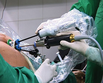
Static seal applications are the most common and include those that prevent fluids and drugs from escaping into or out of a medical device. The seal design can range from basic O-rings to complex shapes. Static seals can be found in the broadest range of medical devices from pumps and blood separators to oxygen concentrators.New advances in trocar designs incorporating specialized seals allow multiple instruments to be inserted in the single trocar. A reciprocating seal application with linear motion would include endoscopes that require trocar seals. These trocar seals are complex in design and allow the surgeon to insert and manipulate instruments to accomplish the medical procedure. These procedures range from relatively simple hernia repairs to the most difficult cardiac procedures. All of these minimally invasive surgeries employ endoscopes with seals that rely on seal stretch, durability and ability to retain shape during lengthy and arduous procedures. This particular seal application combines both reciprocating and rotary motion with the main function being linear motion.
A rotary seal application most commonly includes O-rings used to seal rotating shafts with the turning shaft passing through the inside dimension of the O-ring. Systems utilizing motors such as various types of scanning systems require rotary seals but there are many other non-motorized applications that also require rotary seals. The most important consideration in designing a rotary seal is the frictional heat buildup, with stretch, squeeze and application temperature limits also important.
Function of a particular seal design
What is the function of the seal? It is important to identify specifically if the design must seal a fluid and be impermeable to a particular fluid. Or will the seal transmit a fluid or gas, transmit energy, absorb energy and/or provide structural support of other components in device assembly. All of these factors and combinations need to be thoroughly examined and understood to arrive at successful seal design.
A seal's operating environment
In what environment will a seal operate? Water, chemicals and solvents can cause shrinkage and deformation of a seal. It is important therefore to identify the short and long term effects of all environmental factors including oxygen, ozone, sunlight and alternating effects of wet/dry situations. Equally important are the effects of constant pressure or changing pressure cycle and dynamic stress causing potential seal deformation.
There are temperature limits in which a seal will function properly. Depending on the seal material and design, a rotary shaft seal generally would be limited to an operating temperature range between -30° F and +225°F. To further generalize, the ideal operating temperature for most seals is at room temperature.
Expected seal life - How long must the seal perform correctly?
-
December 06, 2018
The O-Ring & Engineered Seals Division of Parker Hannifin Corporation, the global leader in motion and control technologies, recently announced the launch of VA179, a new extreme high temperature fluorocarbon (FKM) compound. VA179 is an innovative, 70 durometer rubber seal material providing increased high temperature limits while maintaining chemical resistance and low temperature sealing consistent with standard FKMs.
VA179 consists of a breakthrough rubber technology increasing the FKM continuous high temperature limit an additional 20°C (68ºF) over standard FKM materials on the market today. This provides a new industry sealing solution to long-term compression set issues for customers using traditional fluorocarbons and silicones.
"In markets such as aerospace, automotive, and heavy-duty, we are frequently challenged to expand the temperature capabilities of our rubber compounds,” says Nathaniel Sowder, aerospace, military and chemical processing business development engineer, O-Ring & Engineered Seals Division, “With the launch of VA179, we now have a solution that will reach higher temperatures without sacrificing the low temperature and chemical resistance attributes that make standard FKM such a popular choice.”
-
October 23, 2018
Gallagher recently recorded the Rubber Energized Seals webinar, discussing rubber energized rod or piston seals, and the advantages and disadvantages to using some of the most common seal profiles. This webinar is presented in conjunction with one of our trusted partners, Eclipse Engineering, Inc. Eclipse is a designer and manufacturer of high performance engineered polymer
-
September 18, 2018
Gallagher recently recorded the Rubber Energized Seals webinar, discussing rubber energized rod or piston seals, and the advantages and disadvantages to using some of the most common seal profiles. This webinar is presented in conjunction with one of our trusted partners, Eclipse Engineering, Inc.
-
April 03, 2018
Gallagher recently published its Failure Modes of Elastomers in the Semiconductor Industry White Paper, now available for download on our site. This white paper discusses common issues that occur with elastomer seals in the semiconductor industry. The excerpt below is the fourth and final section of our new white paper, discussing Volatiles (offgassing) and Particle Generation. To download the white paper in its entirety, visit our Resources Page, or click on the image to the right.
Failure Modes of Elastomers in the Semiconductor Industry
High performance elastomers are found in many applications in the semiconductor industry (see paper titled Perfluoroelastomers in the Semiconductor Industry). Though perfluoroelastomer (FFKM) seals are formulated to meet the highest performance requirements of integrated circuit (chip) manufacturers, even these elastomers can’t solve every sealing application nor will they last forever in service. Additionally, end users need to understand subtle performance differences between perfluoroelastomers in the same product line. For example, one product may be better at minimizing particle generation while another may be better for high temperature services.