PTFE
- May 30, 2019
Seal designers often feel caught in the constant struggle to balance the demands of a sealing application with physical and material constraints.
At Eclipse, it’s an engineer’s job to understand and weigh these limitations
- March 12, 2019
Freudenberg-NOK Sealing Technologies has begun supplying innovative, lightweight radial shaft seals to a major Detroit-based vehicle manufacturer for installation on the V6 and V8 engines powering its newest pickup trucks and sport utility vehicles (SUVs). Enter the Freudenberg BlueSeal.
The BlueSeal, part of Freudenberg’s award-winning Low Emission Sealing Solution (LESS) portfolio of engine, transmission
- February 19, 2019
A patented lip design and the patented combination of PTFE sealing lip and sliding bearing in the lip seal element provide the new dry running seal "SeccoLip" from EagleBurgmann with particularly high flexibility. These technical features help the lip seal compensate directly and safely radial deflections of the shafts in agitators, mixers and reactors.
The sliding bearing tracks
- February 05, 2019
Compression Packing
How this application fits as a versatile solution.
Stem packing is a familiar product. The most common type is braided compression packing. Braided packing is used in a wide range of applications. Depending on the service, construction materials can be as diverse as plants or animal derivatives, mineral fibers or synthetic plastics and even metal. The process of cutting rings from rope packing, inserting them into a stuffing box and torquing them to the right density is common, but it is not always the best choice.
Another widely used manufacturing method is die-molding. It is the process of wrapping a material around a mandrel, placing it in a die and preforming it to make a seal. Using these and other manufacturing technologies, packing is found to work in applications as different as aerospace, heavy trucking and power generation. A review of some unusual applications demonstrates the versatility of compression packing as a sealing solution.
The Origin of Packing
Compression packing is an ancient technology dating back more than 5,000 years. Boats and ships used a rudder as a steering mechanism. The rudder shaft penetrates the hull of the vessel below the water line, so water can leak into the bilge. Ancient sailors, using the top technology of the day, would take pieces of clothing, sail cloth and rope, cover it with animal fat or wax and stuff it into the gap around the shaft. Eventually, a box was secured around the shaft and a gland, which could be tightened to compress the packing material, was created to improve sealing and longevity. The terms compression packing, stuffing box and gland come from these early sailors.
Compression Packing
Over time, many improvements in packing construction and materials were made. Packing today can be made of flax, Kevlar, polytetrafluoroethylene (PTFE), graphite or metal. It typically has a square cross-section and is sold in precut rings or in large coils, as shown in Image 1. Synthetic aramid fibers are abrasionresistant and can handle higher temperatures and shaft speeds. PTFE has excellent lubricity and chemical resistance. Graphite coupled with mica or an aramid fiber can stave off the heat generated by a rotating shaft and provide long life in challenging applications.
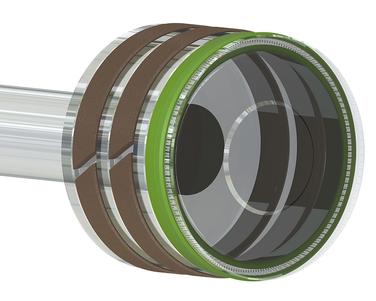
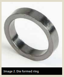
Die-Formed Packing
Die-formed compression packings are excellent in terms of sealing performance and reliability and offer a wide range of long-term, low-emission and low maintenance products. See Image 2.
Not only are die formed rings easier and quicker to install, but the pre-compression increases the density of each ring and reduces the gland loads necessary to seat and compress multiple rings in the stuffing box. The result is lower friction on the shaft or the spindle, with improved sealing performance and a longer life.
Factor in STAMPS
As mentioned in an article previously published by the Fluid Sealing Association, (Sealing Sense, Pumps & Systems, March 2005), there are several key factors to consider when choosing the right packing. They include:
- size or stuffing box bore
- temperature inside the stuffing box application: whether it’s a pump, valve, mixer, refiner, process, characteristics such as pH level and chemical compatibility
- motion: rotary, helical or reciprocal
- pressure inside the stuffing box
- surface speed expressed in feet per minute or meters per second
Keeping this in mind, here are some applications to consider when you are going way beyond the typical stuffing box:
- June 06, 2017
Polytetrafluoroethylene (PTFE) is commonly known as a coating for pans under the DuPont trade name Teflon™. It is also superbly suited as a sealant and is superior to many materials in specific ways. For example, it can be used at low and high temperatures and in combination with gasoline, solvents, water and other polar media such as lyes, standard lubricants and brake fluid. PTFE’s chemical resistance is nearly universal.
History
In 1938, while working for DuPont, American chemist Roy Plunkett was looking for a substitute for the fluorohydrocarbon Freon, which his employer was only allowed to sell to General Motors’ Frigidaire division for patent-related reasons. For his research, he had obtained a supply of tetrafluoroethylene (TFE), which was used as refrigerator coolant. He stored it in small pressurized gas cylinders at low temperatures. When he was ready to use the gas after a fairly long storage period, none was left in the container. But its weight was unchanged. After it was opened, there were white crumbs inside and the inner walls of the container were covered with a thin layer. Plunkett quickly realized that the TFE gas had been polymerized into a plastic. This new plastic, PTFE, proved to be completely resistant to chemical exposure. Not even aqua regia¹ could harm it in any way. But its production was so costly that practical uses seemed inconceivable.
- January 05, 2017
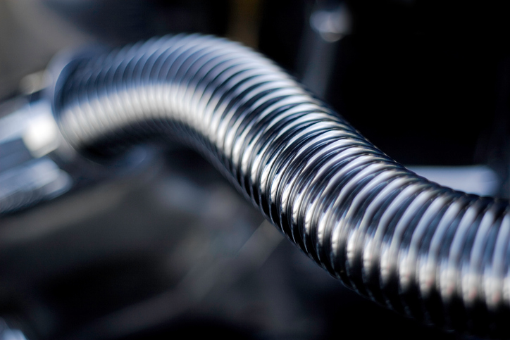
There are many factors to be considered when choosing the right type of hose for your application. There are many different types of hose available on the market. They include metal, rubber, composite, PTFE and fabric. The decision of which hose type to buy depends on the application for which the hose is being used.
Metal hose is ideal for absorbing vibration, misalignment correction, thermal expansion or contraction of piping systems, and protecting equipment from excess motion. Typically, metal hose is used when no other (non-metallic) constructed hose will work. In other words, metal hose is used as a last resort.
Here are some of the factors that should alert you it's time to use metal hose:
- September 01, 2016
In our latest video, Gallagher Fluid Seals Engineering Manager Craig Beil discusses the various PTFE fillers used in making seal materials. Fillers include carbon, glass, stainless steel and molybdenum disulfide. Watch the video to learn more about what PTFE fillers
- August 23, 2016
Today we’ll continue our look at spring-energized seals by exploring some of the preliminary considerations to made when working with these seals.
A spring energized PTFE seal is selected to fit an exact set of service conditions found in your application.
Gallagher Fluid Seals recommends conducting a review of the entire sealing environment. You should use the Engineering Action Request (EAR) form before selecting a seal design.
- April 21, 2016
Today we’ll conclude our series of blog posts on PTFE by discussing some PTFE radial lip seal applications, as well as a brief look at wear sleeves.
PTFE has superior mechanical and physical properties and chemical resistance, which means the areas where PTFE radial lip seals are used is growing. These areas include:
Diesel Engine Applications
These consist of the front and rear crankshaft, accessory drive, and blower and thermostat seals. PTFE seals are used and tested in these areas because they can meet the performance and life requirements of modern engines.
Minimum wear, performance at high temperatures with limited lubrication, resistance to abrasive contaminants and fluid compatibility are the main factors for PTFE’s use in these applications.
- April 14, 2016
Today we’ll continue our look at PTFE rotary seals by focusing on three areas: housing/bore considerations, pressure and shaft velocity and shaft misalignment and runout.
Housing/Bore Considerations
Typical PTFE rotary lip seals are pressed into the bore to assure proper OD sealing and seal retention in the housing. Most seal and housings are made from steel and cast iron. Take care when softer materials – aluminum, bronze, plastic – are used for the housing. Aluminum has a thermal expansion rate almost double that of steel. Metal case designs can lose the required press fit in an aluminum housing when they go through thermal cycles due to the higher rate of thermal expansion of aluminum.
A finish range of 32 to 63 μin Ra (0.8 to 1.6 μin Ra) is recommended for service pressures up to 3 psi (0.20 bar). For thicker fluids such as grease, a 125 μin Ra (3.17 μin Ra) finish would be acceptable with no system pressure.
A lead in chamfer is strongly recommended for all seal housings. The chamfer aligns the seal during installation and helps keep the seal from cocking. Both corners of the chamfer should be free of burrs or sharp edges. For pressurized rotary applications, take additional precautions to ensure the seal isn’t pushed from the housing.


